Radar Level Transmitter Disadvantages
Radar Level Transmitter Disadvantages: An Engineering Guide to Limitations and Selection
In the landscape of industrial automation, radar technology is often regarded as the gold standard for non-contact level measurement. Its ability to operate through vacuums, high pressures, and extreme temperatures makes it a preferred choice for many process engineers. However, no single technology is universal. To ensure the reliability of a control system, it is critical to understand the specific radar level transmitter disadvantages and technical boundaries that can lead to measurement errors or equipment failure.
At levelmeter.org, we prioritize practical engineering accuracy. This guide examines the physical and economic limitations of radar level measurement to help procurement and technical teams make informed decisions when specifying Radar Level Meters.
Understanding Radar Measurement Principles
Before discussing limitations, we must establish how these instruments function. Industrial radar level transmitters generally utilize one of two primary technologies: Time of Flight (ToF) Pulse Radar or Frequency Modulated Continuous Wave (FMCW) Radar.
Pulse Radar (Time of Flight)
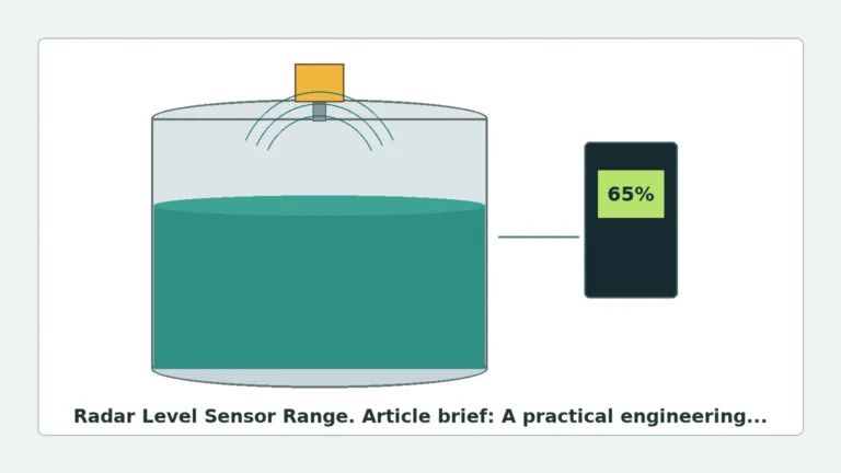
Pulse radar emits a high-frequency microwave signal toward the medium's surface in short bursts. The instrument measures the time it takes for the pulse to travel to the surface and reflect back to the sensor. Since the speed of light ($c$) is constant, the distance ($D$) is calculated as $D = (c \times t) / 2$.
FMCW Radar
FMCW radar emits a continuous signal with a constantly changing frequency. The difference in frequency between the transmitted signal and the reflected signal (the "beat frequency") is proportional to the distance. FMCW is generally more accurate and provides a better signal-to-noise ratio than pulse radar, though it typically carries a higher price point.
In both cases, the success of the measurement depends on the signal's ability to reflect off the product surface and return to the antenna with sufficient strength to be distinguished from background noise.
Primary Radar Level Transmitter Disadvantages
While radar is robust, several factors can impede its performance. These range from the physical properties of the medium to the geometry of the vessel.
1. Sensitivity to Dielectric Constants ($\epsilon_r$)
The most significant limitation of non-contact radar is its dependence on the dielectric constant of the measured material. The dielectric constant is a measure of a material's ability to reflect electromagnetic energy.
* High Dielectric Materials: Water ($\epsilon_r \approx 80$) and aqueous solutions reflect radar waves very effectively.
* Low Dielectric Materials: Hydrocarbons, oils, and certain solids (like plastic pellets) have low dielectric constants ($\epsilon_r < 2.0$).
If the dielectric constant is too low, the microwave signal penetrates the material rather than reflecting off the surface. This results in a weak return signal that may be lost in the electronic noise of the tank. For materials with $\epsilon_r$ below 1.4, standard non-contact radar often fails unless a Guided Wave Radar (GWR) or a high-sensitivity FMCW unit is used.
2. The Impact of Heavy Foam and Turbulence
Radar waves are electromagnetic, not mechanical. While they can pass through thin layers of mist or light foam, dense and thick foam poses a significant challenge.
* Absorption: Dense foam can absorb the microwave signal entirely, preventing any reflection from reaching the sensor.
* Refraction: Complex foam structures can scatter the signal in multiple directions, leading to a "lost signal" error.
* Turbulence: Rapidly agitating surfaces or vortexes created by mixers can deflect the radar beam away from the antenna. While software algorithms can smooth out some of these fluctuations, extreme turbulence reduces the overall accuracy and response time of the transmitter.
3. Beam Spread and Internal Obstructions
Every radar antenna has a specific beam angle, typically ranging from 3° to 20°. As the distance from the sensor increases, the diameter of the radar beam expands.
If the beam encounters internal tank structures—such as heating coils, agitator shafts, ladders, or support struts—it creates "ghost echoes." While modern Radar Level Meters include "false echo suppression" software to map out these obstructions, the presence of these objects still degrades the signal quality and can lead to measurement instability if the product level is near the obstruction.
4. Installation Constraints and Nozzle Interference
The physical mounting of the radar unit is a common source of failure. Radar transmitters have a "dead zone" or "blocking distance" near the antenna (typically 50mm to 500mm) where measurement is impossible.
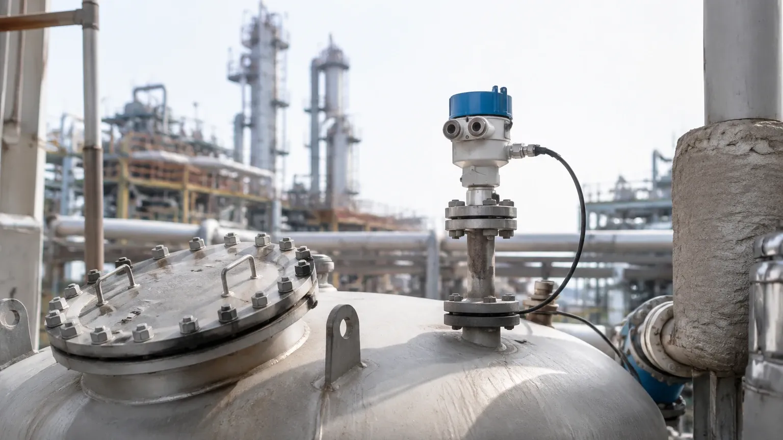
Furthermore, if a radar is mounted on a tall, narrow nozzle, the microwave signal can reflect off the internal walls of the nozzle before it even enters the tank. This creates a large interference signal at the top of the tank, effectively increasing the dead zone and preventing accurate measurement when the tank is nearly full.
5. Higher Initial Capital Expenditure (CAPEX)
Compared to ultrasonic sensors, hydrostatic pressure transmitters, or float-based systems, radar technology is expensive. The complexity of the high-frequency electronics and the materials required for chemical-resistant antennas (such as PTFE or Hastelloy) result in a higher purchase price. For simple water storage applications where high precision isn't required, the cost of radar may not be justified by the ROI.
Comparison Table: Radar vs. Alternative Technologies
| Feature | Non-Contact Radar | Guided Wave Radar (GWR) | Ultrasonic | Hydrostatic Pressure |
| :— | :— | :— | :— | :— |
| Accuracy | High (±1mm to ±5mm) | High (±2mm) | Moderate (±0.25% of range) | Moderate |
| Vacuum Suitability | Excellent | Excellent | Poor (Requires air) | Good |
| Foam Resistance | Low to Moderate | High | Very Low | Excellent |
| Cost | High | High | Medium | Low |
| Maintenance | Very Low | Low (Probe cleaning) | Low | Moderate (Diaphragm wear) |
| Dielectric Dependency | High | Moderate | None | None |
Installation Considerations to Mitigate Disadvantages
To overcome the inherent radar level transmitter disadvantages, engineers must follow strict installation protocols:
1. Nozzle Geometry: Ensure the nozzle diameter is large enough for the beam angle and that the antenna extends slightly past the bottom of the nozzle to prevent ringing.
2. Positioning: Mount the sensor at 1/4 to 1/3 of the tank diameter away from the wall. Never mount the sensor in the center of a domed tank, as this can concentrate parasitic reflections.
3. Frequency Selection: Use higher frequency radar (e.g., 80 GHz) for narrow tanks or vessels with many internal obstructions, as the beam angle is much tighter (often 3°).
4. Stilling Wells: For extremely turbulent surfaces or low-dielectric liquids, installing the radar inside a stilling well (a vertical pipe) can concentrate the signal and eliminate surface ripples.
Limitations in Solid and Powder Measurement
When measuring solids, such as grain, cement, or plastic pellets, radar faces additional hurdles:
* Angle of Repose: Unlike liquids, solids form cones or depressions. If the radar beam hits a sloped surface, the signal may reflect toward the tank wall rather than back to the sensor.
* Dust Attenuation: While radar penetrates dust better than ultrasonic waves, extremely high-density dust clouds (during pneumatic filling) can still attenuate high-frequency signals (especially 80GHz variants).
Frequently Asked Questions (FAQ)
Q: Can radar level transmitters measure through plastic tank walls?
A: Yes, provided the plastic is non-conductive and the dielectric constant is low. This allows for measurement without a tank opening, though signal strength will be reduced.
Q: Is radar affected by temperature and pressure changes?
A: Unlike ultrasonic sensors, which depend on the speed of sound (which varies with air density), radar uses electromagnetic waves. These waves are virtually unaffected by changes in temperature, pressure, or the presence of vapors/gases.
Q: Why would I choose Guided Wave Radar over Non-Contact Radar?
A: Guided Wave Radar (GWR) is preferred when dealing with very low dielectric constants, heavy foam, or extremely turbulent surfaces, as the probe physically guides the signal to the surface and back.
Q: What is the minimum dielectric constant for a standard radar?
A: Most modern 26GHz or 80GHz Radar Level Meters can handle materials with a dielectric constant as low as 1.4 to 1.9, depending on the antenna gain and signal processing capabilities.
Conclusion
Radar level transmitters offer unparalleled performance in many challenging environments, but they are not immune to the laws of physics. The primary radar level transmitter disadvantages—sensitivity to low dielectric constants, signal absorption by dense foam, and susceptibility to internal obstructions—must be weighed against the application's requirements.
By selecting the correct frequency, antenna type, and mounting location, most of these limitations can be successfully mitigated. For engineers and procurement specialists, the key is to provide the manufacturer with accurate medium data (dielectric constant, viscosity, and foam potential) and vessel drawings before finalizing equipment selection.