Flow Meter Thermal
Flow Meter Thermal
Thermal mass flow meters (TMFMs) represent a specialized category of industrial instrumentation designed to measure the mass flow rate of fluids, primarily gases, by utilizing the heat transfer properties of the medium. Unlike volumetric flow meters, which require additional pressure and temperature compensation to calculate mass, a flow meter thermal provides direct mass flow data. This capability is critical in industrial automation, chemical processing, and water treatment, where the density of gas fluctuates significantly with environmental changes.
In the context of modern process control, integrating accurate gas flow data with liquid level monitoring is essential for comprehensive facility management. While specialized manufacturers like Welk provide robust solutions for liquid measurement via radar and ultrasonic sensors, understanding the thermal mass flow principle is equally vital for engineers managing gas-phase components in the same systems.
Understanding the Measurement Principle of Thermal Flow Meters
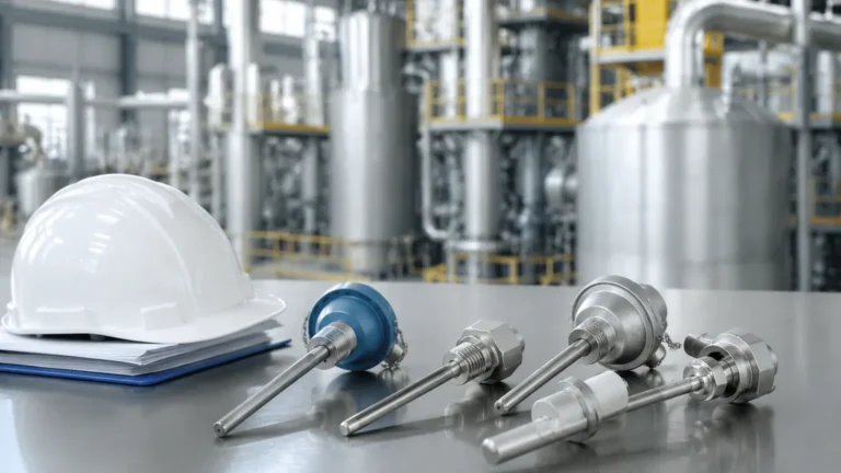
The operation of a flow meter thermal is based on the physical principle of convective heat transfer. Specifically, it relies on the fact that a moving fluid will absorb heat from a heated surface at a rate proportional to its mass flow. Most industrial thermal flow meters employ two Resistance Temperature Detectors (RTDs) as sensors.
The Two-Sensor Method
1. Reference Sensor: This RTD measures the actual temperature of the process gas. It provides a baseline for the system.
2. Active (Heated) Sensor: This RTD is heated to a specific temperature above the reference sensor.
As gas flows past the heated sensor, molecules carry away heat—a process known as "heat dissipation." The electronics of the meter must then provide more power to the heated sensor to maintain the temperature difference (ΔT) between the two sensors. The amount of electrical power required to maintain this constant ΔT is directly proportional to the mass flow rate of the gas. This relationship is often described by King’s Law, which mathematically relates the heat loss to the fluid velocity and density.
Constant Temperature vs. Constant Current
There are two primary electronic configurations for these meters:
* Constant Temperature Differential: The circuit maintains a fixed temperature difference between the sensors. The power required to maintain this difference is the measurement signal. This is the most common method due to its high sensitivity and fast response time.
* Constant Current: The circuit provides a fixed amount of power to the heated sensor, and the resulting temperature difference is measured. This method is less common in high-precision industrial applications but is sometimes used in simpler configurations.
Key Types of Thermal Mass Flow Meters: In-line vs. Insertion
Selecting the correct physical configuration is the first step in ensuring long-term reliability. The choice usually depends on pipe diameter, flow range, and maintenance requirements.
In-Line Thermal Flow Meters
In-line models consist of a flow body that is flanged or threaded directly into the piping system. These are typically used for smaller pipe diameters, generally ranging from 15 mm to 100 mm.
* Advantages: They often include built-in flow conditioners to stabilize the flow profile, leading to higher accuracy and better repeatability.
* Applications: High-precision laboratory gases, chemical dosing, and small-scale compressed air monitoring.
Insertion Thermal Flow Meters
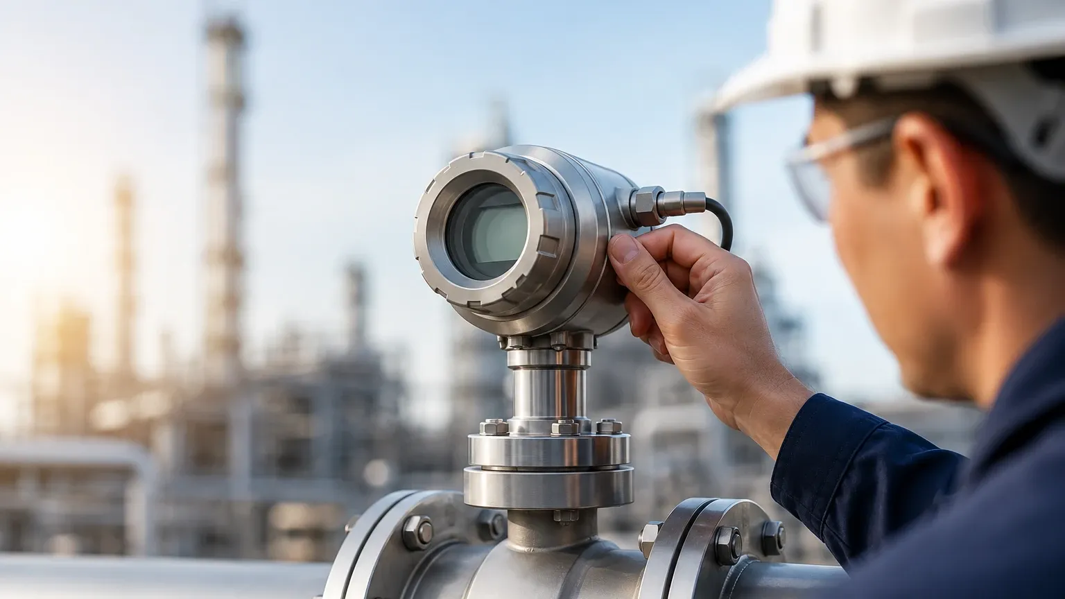
Insertion meters feature a probe that is inserted through a mounting fitting (such as a ball valve or NPT thread) into the center of a pipe or duct.
* Advantages: They are cost-effective for large pipe diameters (100 mm to several meters) and can often be installed or removed under pressure (hot-tapping) without shutting down the process.
* Applications: Large-scale aeration tanks in water treatment, stack gas monitoring, and main natural gas lines.
| Feature | In-Line Flow Meter | Insertion Flow Meter |
| :— | :— | :— |
| Pipe Size Range | 15 mm – 100 mm | 100 mm – 4,000+ mm |
| Installation | Requires pipe cutting | Requires a single tap/fitting |
| Accuracy | Generally higher (±1% of reading) | Moderate (±1% reading + 0.5% FS) |
| Pressure Drop | Low to Moderate | Negligible |
| Cost | Increases with pipe size | Relatively constant regardless of size |
Selection Criteria for Industrial Applications
When evaluating a flow meter thermal for a specific project, engineers must confirm several technical parameters. Because these meters are "gas-specific," a unit calibrated for nitrogen will not read accurately if used for carbon dioxide without recalibration.
1. Gas Composition and Specific Heat
The thermal properties of a gas, specifically its specific heat ($C_p$) and thermal conductivity, dictate how much heat it can carry away. If the gas composition is variable (e.g., biogas or flare gas), the meter must be programmed with the specific gas mixture ratios to maintain accuracy.
2. Turndown Ratio
One of the greatest strengths of thermal technology is its exceptional turndown ratio, often reaching 100:1 or even 1000:1. This allows the meter to detect very low leak rates or "zero flow" conditions that would be invisible to Vortex or Differential Pressure (DP) meters. This is particularly useful in compressed air audits and safety-critical leak detection.
3. Process Temperature and Pressure
Standard thermal flow meters typically handle temperatures up to 200°C, though specialized high-temperature versions exist. While mass flow measurement is independent of pressure, the physical construction of the sensor must be rated for the maximum system pressure, often up to 40 bar or higher in industrial gas applications.
4. Integration with Level Measurement
In many B2B industrial environments, flow measurement is one half of a larger mass balance equation. For example, in a chemical reactor, the rate of gas injection (measured by a thermal flow meter) must be balanced against the liquid level changes. For engineers looking to optimize these complex systems, reviewing the Main Page of a dedicated instrumentation manufacturer like Welk provides insights into how level and flow data can be synchronized for better process automation.
Installation Guidelines and Best Practices
Even the most accurate flow meter thermal will fail to perform if installation guidelines are ignored. Thermal meters are sensitive to the "flow profile," which is the velocity distribution of the gas across the pipe's cross-section.
Straight Run Requirements
To ensure a fully developed laminar flow profile, the meter requires a specific length of straight pipe before and after the sensor:
* Upstream: Minimum 10 to 20 diameters (10D – 20D) of straight pipe, depending on the presence of elbows or valves.
* Downstream: Minimum 5 diameters (5D) of straight pipe.
If these distances cannot be met due to space constraints, flow conditioners (perforated plates) must be installed to eliminate turbulence and swirl.
Orientation and Positioning
* Horizontal Piping: The sensor should ideally be installed on the side of the pipe (3 o'clock or 9 o'clock position) to prevent moisture or condensate from pooling on the sensor tips.
* Vertical Piping: Flow should ideally be upward to ensure a consistent profile and to prevent any liquid droplets from falling back onto the sensor.
Cleanliness and Moisture
Thermal meters work best with clean, dry gases. If the gas contains significant moisture (condensate), the water droplets hitting the heated sensor will cause a massive "spike" in the flow reading because water absorbs much more heat than gas. In such cases, moisture separators or heated sensor tips may be required.
Limitations and Operational Risks
While highly versatile, the flow meter thermal is not a universal solution for every application. Engineers should be aware of the following limitations:
* Composition Sensitivity: If the gas mixture changes unexpectedly (e.g., a shift in the methane/CO2 ratio in biogas), the meter's calibration becomes invalid. Continuous gas analysis may be required to correct the flow data.
* Coating and Fouling: In dirty gas applications (like raw sewage gas), particles can coat the sensor. This coating acts as an insulator, slowing the heat transfer and causing the meter to read lower than the actual flow. Periodic cleaning or the use of automated retractable probes is recommended.
* Liquid Phase Interference: These meters cannot measure liquid flow or steam. They are strictly for gas-phase applications.
Frequently Asked Questions (FAQ)
Q: Does a thermal flow meter require pressure compensation?
A: No. Because it measures the heat transfer related to the number of molecules (mass) passing the sensor, it inherently accounts for changes in pressure and temperature. However, the gas must be within the calibrated range for specific heat.
Q: Can I use one meter for multiple gases?
A: Only if the meter has multiple gas profiles stored in its electronics. Most high-end industrial meters allow the user to select from a library of common gases (Air, N2, O2, Ar, CO2).
Q: How often should a flow meter thermal be recalibrated?
A: For regulated industries or safety-critical applications, annual calibration is standard. In stable, clean-gas environments, the interval may be extended to 2-3 years, provided the sensor is inspected for fouling.
Q: What is the typical accuracy of these meters?
A: Most industrial-grade thermal mass flow meters offer an accuracy of ±1% of the reading plus ±0.5% of the full-scale range.
Conclusion and Next Steps
The flow meter thermal is an indispensable tool for precise gas management, offering direct mass flow measurement and high sensitivity at low flow rates. When integrated into a broader process control strategy—alongside reliable level measurement instruments for liquid phases—it enables facilities to achieve higher efficiency and better safety standards.
For project managers and engineers specifying new systems, it is essential to verify the gas composition and pipe geometry before purchase. To explore how these flow technologies complement advanced liquid level monitoring solutions, professionals are encouraged to review product options and application support on the Main Page of industry-leading instrumentation providers. By selecting the right technology for each phase of the process, industrial operators can ensure long-term accuracy and reduced maintenance costs.