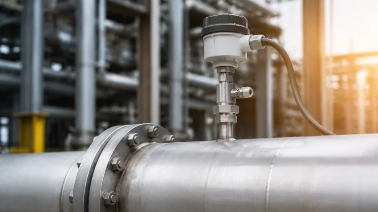
Fmp51
Fmp51
In the landscape of industrial process automation, precise level measurement is a cornerstone of safety, efficiency, and inventory management. Among the various technologies available, Guided Wave Radar (GWR) has emerged as a preferred solution for challenging environments involving high temperatures, high pressures, and complex fluid dynamics. The fmp51 represents a specific standard in high-performance GWR instrumentation, designed primarily for liquid level and interface measurement in the oil and gas, chemical, and power industries. This guide examines the technical foundations, selection criteria, and practical application of GWR technology as embodied by the fmp51 series.
The Principle of Guided Wave Radar (GWR) Measurement
To understand the capabilities of the fmp51, one must first understand the physics of Time Domain Reflectometry (TDR), which is the underlying principle of Guided Wave Radar. Unlike non-contact radar, which broadcasts electromagnetic waves through the air, GWR utilizes a physical probe—a rod, cable, or coaxial tube—to guide high-frequency electromagnetic pulses from the transmitter to the process medium.
The TDR Process
1. Pulse Emission: The electronics in the transmitter head generate low-energy electromagnetic pulses (typically in the GHz range).
2. Propagation: These pulses travel down the probe at the speed of light.
3. Reflection: When the pulse encounters a change in the dielectric constant ($ε_r$) of the surrounding medium—such as the transition from air or vapor to a liquid surface—a portion of the pulse energy is reflected back toward the transmitter.
4. Detection and Calculation: The transmitter measures the time elapsed between the emission of the pulse and the receipt of the reflection. Because the speed of light is constant, the distance to the surface is calculated as:
*Distance = (Speed of Light × Time-of-Flight) / 2*.
Because the pulses are contained and guided by the probe, the signal is significantly less affected by turbulence, foam, or internal tank obstructions compared to non-contact radar. This makes instruments like the fmp51 exceptionally reliable in narrow nozzles or tanks with complex internal geometries.
Technical Specifications and Evaluation Criteria
When evaluating a GWR transmitter like the fmp51, engineers must align the instrument's specifications with the specific demands of the process. The fmp51 is specifically engineered for high-temperature and high-pressure applications where standard sensors might fail.
Material and Pressure Ratings
Industrial processes often involve corrosive media or extreme pressures. The fmp51 typically features a variety of wetted materials, including 316L stainless steel and Alloy C22, with specialized seals such as Kalrez or Graphite to withstand temperatures ranging from -196°C to +450°C (-320°F to +842°F). Pressure ratings can extend up to 400 bar (5,800 psi), making it suitable for high-pressure steam boilers and chemical reactors.
Dielectric Constant (ε_r) Requirements
The dielectric constant of the medium is the most critical factor in signal reflection. Water has a high dielectric constant (ε_r ≈ 80), providing a very strong reflection. Conversely, hydrocarbons and oils have low dielectric constants (ε_r ≈ 1.4 to 4.0), which reflect less energy. The fmp51 is designed with high sensitivity to detect these weak reflections, but users must ensure the medium meets the minimum ε_r threshold specified for the chosen probe type.
Probe Selection and Application Suitability
The choice of probe is fundamental to the performance of the fmp51. The probe acts as the interface between the electronics and the process, and its geometry determines how the electromagnetic field interacts with the environment.
| Probe Type | Best For | Advantages | Limitations |
| :— | :— | :— | :— |
| Mono-Rod | General liquids, viscous fluids | Easy to clean; resistant to build-up | Sensitive to nozzle interference; requires larger clearance |
| Rope (Cable) | Tall silos or deep tanks | Can reach lengths up to 45m (148 ft); easy to transport | Susceptible to swinging in high-flow areas; requires a weight |
| Coaxial | Low dielectric liquids, turbulence | Highest signal-to-noise ratio; immune to nozzle effects | Prone to clogging if the liquid contains solids or is highly viscous |
For engineers seeking to compare these probe types against other measurement technologies, such as ultrasonic or hydrostatic sensors, the Main Page of our technical resource offers detailed comparisons and product data sheets to assist in the selection process.
Interface Measurement Capabilities
One of the primary reasons for selecting the fmp51 is its ability to measure both the total level and the interface level between two immiscible liquids (e.g., oil over water).
In interface measurement, the electromagnetic pulse passes through the upper liquid layer (which must have a lower dielectric constant and be non-conductive) and reflects off the lower liquid layer (which must have a higher dielectric constant).
Key requirements for successful interface measurement:
* The upper layer must be non-conductive.
* The difference in dielectric constants between the two layers should be at least 10.
* The upper layer thickness must be at least 60 mm (2.4 inches) for the instrument to distinguish between the two reflections.

Installation Considerations and Best Practices
Proper installation is critical to avoid "false echoes" and ensure the longevity of the fmp51. Even though GWR is more forgiving than non-contact radar, certain physical boundaries must be respected.
Nozzle Geometry
The diameter and height of the mounting nozzle can influence the signal. For rod and rope probes, the nozzle should be as short and wide as possible. If a long, narrow nozzle is unavoidable, a coaxial probe or a software-based "mapping" of the nozzle reflection may be required to prevent interference near the top of the tank.
Internal Obstructions
The probe should be installed at a distance from tank walls and internal structures (ladders, agitators, heating coils). A general rule of thumb is to maintain a minimum clearance of 300 mm (12 inches) from the tank wall for rod probes, though this varies based on the tank material and probe type.
Bypass Pipes and Stillwells
In applications with heavy surface foam or extreme turbulence, the fmp51 is often installed in a bypass pipe (external to the tank) or a stillwell (internal pipe). This creates a calm surface for measurement and concentrates the radar signal, allowing for more accurate readings of low-dielectric fluids.
Limitations and Potential Risks
While the fmp51 is a robust instrument, it is not universal. Understanding its limitations prevents costly measurement errors.
1. Build-up and Bridging: While GWR can handle some coating on the probe, significant build-up of conductive material can cause signal attenuation or "ghost" levels. In such cases, mono-rod probes are preferred over coaxial probes as they are easier to clean.
2. Probe Stress: In high-flow tanks or vessels with agitators, the lateral forces on a long rod or rope probe can be significant. Mechanical support (such as a centering disk or end-of-probe anchoring) may be necessary to prevent the probe from breaking or hitting the tank wall.
3. Vapor Phase Compensation: In high-pressure steam applications (e.g., boiler drum level), the high density of the steam can slow down the radar pulse, leading to a measurement error. Higher-end versions of the fmp51 offer a reference rod for vapor compensation to automatically correct this error.
Frequently Asked Questions (FAQ)
Q: Can the fmp51 be used in vacuum conditions?
A: Yes. Since GWR does not rely on air or gas for pulse propagation, it functions perfectly in vacuum conditions. The primary concern in vacuum applications is the integrity of the process seal at the transmitter head.
Q: How does foam affect the measurement?
A: GWR is generally superior to ultrasonic or non-contact radar in foamy applications. Depending on the density and conductivity of the foam, the pulse will either pass through it to the liquid surface or reflect off the top of the foam. In many cases, it provides a stable reading where other technologies fail.
Q: Can the probe be shortened in the field?
A: Most rod and rope probes for the fmp51 are designed to be field-cuttable. However, after shortening the probe, the device configuration must be updated to reflect the new probe length to maintain accuracy.
Q: Is grounding necessary for the fmp51?
A: Yes, proper grounding is essential for both safety and signal integrity. The instrument should be grounded to the metal tank or, in the case of plastic tanks, a ground reference (like a metal flange or rod) must be provided.
Q: What is the "Upper Blocking Distance"?
A: This is the area at the very top of the probe where measurement is not possible or is less accurate. It is typically defined by the nozzle height and the transition from the transmitter electronics to the probe. This must be accounted for in tank capacity calculations.
Conclusion and Next Steps
The fmp51 remains a benchmark for guided wave radar technology, offering a balance of durability and precision for the most demanding industrial sectors. By understanding the interaction between the probe geometry and the dielectric properties of the process media, engineers can implement a level measurement solution that minimizes maintenance and maximizes uptime.
For those currently in the design or replacement phase of a project, reviewing the full range of radar, ultrasonic, and magnetic level solutions is recommended. To explore specific product configurations, technical drawings, and global support options, please visit our Main Page for comprehensive engineering resources and product support.