Co2 Supply Chain
Co2 Supply Chain
The global transition toward a low-carbon economy has transformed the CO2 supply chain from a niche industrial gas segment into a critical pillar of global climate strategy. Carbon Capture, Utilization, and Storage (CCUS) requires a robust infrastructure to move carbon dioxide from emission sources to end-use sites or permanent sequestration reservoirs. Within this complex logistics network, accurate level measurement is not merely a matter of inventory management; it is a fundamental requirement for safety, fiscal accounting, and process stability.
In the CO2 supply chain, carbon dioxide is handled in various states—gas, liquid, and supercritical fluid. Each phase presents unique challenges for instrumentation. This guide examines the technological requirements for monitoring CO2 levels across the supply chain, providing engineering insights into sensor selection and application.
Understanding the Infrastructure of the CO2 Supply Chain
The CO2 supply chain is a multi-stage system designed to handle massive volumes of gas under varying thermal and barometric conditions. The journey typically begins at a capture facility, such as a hydrogen plant, cement kiln, or power station, and ends in deep geological formations or industrial manufacturing processes.
1. Capture and Compression
After CO2 is captured, it must be dehydrated and compressed. Compression reduces the volume significantly, often reaching pressures above 73.8 bar (the critical point), where CO2 becomes a supercritical fluid. Level measurement in capture tanks and knock-out drums is essential to prevent liquid carryover into compressors.
2. Intermediate Storage
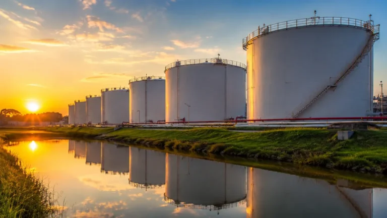
Liquid CO2 is commonly stored in horizontal or vertical vacuum-insulated tanks (bullets). These tanks are typically maintained at pressures of 15 to 25 bar and temperatures between -20°C and -30°C. Maintaining the "cold box" environment is vital to prevent boil-off gas (BOG) and overpressure events.
3. Transportation (Pipelines, Ships, and Trucks)
Large-scale transport via pipeline requires constant pressure monitoring, while transport via ship or truck relies on accurate level sensing to ensure safe loading limits (ullage) are not exceeded. Overfilling a CO2 tank can lead to catastrophic structural failure if the liquid expands due to temperature rise.
4. Utilization and Sequestration
In the utilization phase, CO2 is used in food and beverage carbonation, chemical synthesis, or enhanced oil recovery (EOR). In sequestration, it is injected into saline aquifers or depleted oil fields. In all cases, the Main Page of an industrial facility's control system must have real-time, reliable data to manage these flows.
Measurement Principles for Carbon Dioxide Storage
Selecting the right measurement principle depends on the physical state of the CO2 and the vessel's design. Below are the primary technologies used in the CO2 supply chain.
Radar Level Measurement (ToF)
Radar transmitters work on the Time-of-Flight (ToF) principle. They emit high-frequency microwave pulses (typically 26GHz or 80GHz) that reflect off the surface of the liquid CO2.
* Non-Contact Radar: This is preferred for bulk storage because it has no moving parts and does not touch the medium. However, CO2 has a low dielectric constant ($\\epsilon_r \\approx 1.6$), which means the reflected signal is weak. High-sensitivity 80GHz radars are often required to track the surface accurately through the vapor space.
* Guided Wave Radar (GWR): GWR uses a probe to guide the microwave signal. This provides a stronger reflection, making it highly reliable for low-dielectric liquids like CO2, even in the presence of turbulence or foam.
Hydrostatic Pressure Measurement
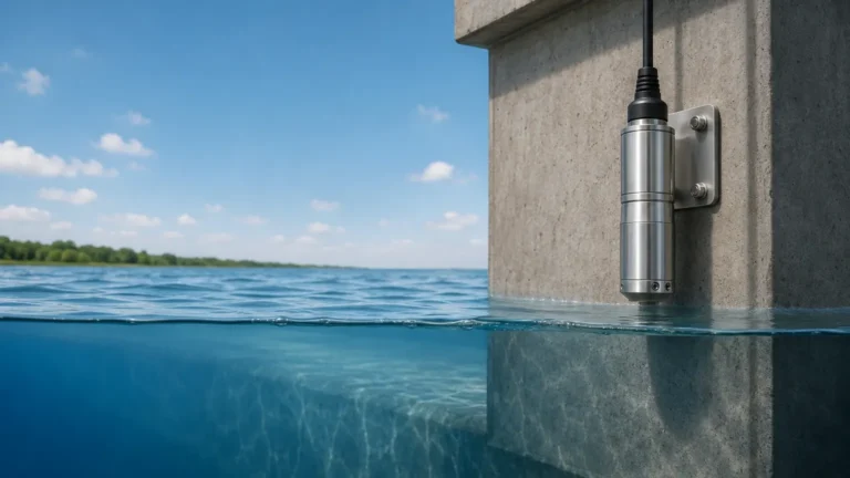
This principle measures the pressure exerted by the liquid column. For pressurized CO2 tanks, a differential pressure (DP) measurement is required. One sensor measures the pressure at the bottom (liquid + gas head), and the other measures the gas head pressure only. The difference between the two, divided by the liquid density, provides the level.
Ultrasonic Level Sensors
Ultrasonic sensors emit sound waves that reflect off the liquid surface. While cost-effective for atmospheric water tanks, they are rarely used in high-pressure CO2 supply chains. The high-density vapor phase in CO2 tanks significantly alters the speed of sound, leading to massive measurement errors unless complex temperature and pressure compensation is applied.
Magnetic Level Gauges (MLG)
MLGs consist of a bypass chamber containing a float with an internal magnet system. As the CO2 level rises and falls, the float moves, flipping magnetic flags on an external scale. This provides a clear visual indication without requiring power. When paired with a reed chain or magnetostrictive transmitter, it provides a redundant electronic signal for the control room.
Comparative Analysis of Level Measurement Technologies
| Technology | Suitability for CO2 | Measurement Principle | Key Advantage | Major Limitation |
| :— | :— | :— | :— | :— |
| 80GHz Radar | Excellent | Non-contact Microwaves | High accuracy, no maintenance | Sensitive to low dielectric constants |
| Guided Wave Radar | Excellent | Contact Microwaves | Strong signal reflection | Probe can be damaged by heavy turbulence |
| Differential Pressure | Good | Hydrostatic Pressure | Proven technology | Requires accurate density data |
| Magnetic Gauge | Excellent | Magnetic Coupling | Visual + Electronic redundancy | Mechanical moving parts (float) |
| Ultrasonic | Poor | Acoustic Waves | Low cost | Inaccurate in pressurized gas phases |
Critical Selection Criteria for CO2 Applications
When engineering a level solution for the CO2 supply chain, several technical factors must be prioritized to ensure long-term reliability.
Dielectric Constant ($\\epsilon_r$)
Liquid CO2 is a non-polar molecule with a very low dielectric constant. In radar applications, this means most of the energy passes through the liquid rather than reflecting back to the sensor. Engineers must specify "low-dielectric" versions of radar sensors or utilize Guided Wave Radar to ensure a sufficient signal-to-noise ratio.
Pressure and Temperature Ratings
CO2 storage tanks are pressure vessels. Instruments must be rated for at least 40 bar for standard liquid storage and up to 250 bar for supercritical transport lines. Furthermore, the seals (O-rings) must be compatible with CO2. Standard elastomers may suffer from "Explosive Decompression" (ED) where CO2 gas permeates the seal and expands rapidly when pressure is dropped, destroying the seal.
Phase Transition and Density
The density of CO2 changes significantly with temperature. Since hydrostatic (DP) transmitters calculate level based on density ($P = \\rho gh$), any temperature fluctuation will cause a level error. If using DP, integrated temperature compensation is mandatory.

Installation and Maintenance Best Practices
Proper installation is as critical as sensor selection. The following guidelines should be followed for CO2 infrastructure:
1. Nozzle Geometry: For radar sensors, ensure the nozzle is short and the inner diameter is smooth to prevent false reflections (ringing). For 80GHz radar, a 50mm (2") or 80mm (3") nozzle is typically sufficient.
2. Stilling Wells: In tanks with high turbulence or internal obstructions, installing a radar sensor inside a stilling well (a vertical pipe) can stabilize the surface and amplify the signal reflection.
3. Insulation: CO2 tanks are often refrigerated. Ensure that the instrument mounting (flange) is properly insulated to prevent ice buildup, which can interfere with the sensor's electronics or block the radar signal.
4. Redundancy: In the CO2 supply chain, a single point of failure can lead to safety shutdowns. Combining a non-contact radar with a magnetic level gauge provides both an electronic signal for the PLC and a physical visual check for operators.
Challenges and Limitations in High-Pressure CO2 Monitoring
The most significant challenge in the CO2 supply chain is the "Supercritical Phase." When CO2 exceeds 31.1°C and 73.8 bar, the distinction between liquid and gas disappears. In this state, traditional "level" measurement is no longer applicable because there is no surface to reflect a signal. In these scenarios, mass flow meters or point density sensors are used instead of level meters.
Another limitation involves boil-off gas. If the refrigeration system of a CO2 tank fails, the liquid begins to boil, creating heavy foam. This foam can absorb radar signals and cause "loss of echo." Selecting a radar with advanced signal processing (algorithms that can track the "true" level through foam) is essential for these emergency conditions.
Frequently Asked Questions (FAQ)
Q: Can I use a standard water level sensor for liquid CO2?
A: No. Liquid CO2 has a different density, a much lower dielectric constant, and is stored under pressure. Standard sensors will likely fail due to seal incompatibility or provide highly inaccurate readings.
Q: Why is 80GHz radar preferred over 26GHz for CO2?
A: 80GHz radar has a narrower beam angle and higher sensitivity. This allows it to focus better on the weak reflection provided by the low-dielectric CO2 surface and avoid interference from tank walls or internal structures.
Q: How do I handle ice formation on the sensor?
A: Use a sensor with a PTFE or PEEK lens antenna. These materials are non-stick. Additionally, ensuring the nozzle is part of the tank's insulation envelope helps maintain the temperature and prevents condensation from freezing on the antenna.
Q: What is the best way to calibrate a CO2 level meter?
A: For radar, calibration is done via software by setting the "empty" and "full" distances. For hydrostatic sensors, you must calibrate the zero and span based on the specific gravity of CO2 at the operating temperature (e.g., 1030 kg/m³ at -20°C).
Conclusion
As the CO2 supply chain continues to scale globally, the demand for precision instrumentation grows. From capture to sequestration, the ability to monitor levels accurately ensures that this critical greenhouse gas is handled safely and efficiently. By understanding the physics of CO2—specifically its low dielectric constant and density sensitivity—engineers can select the appropriate radar, hydrostatic, or magnetic measurement technology to meet the rigorous demands of industrial carbon management. For those seeking to optimize their measurement strategy, it is advisable to Review product options and application support to ensure the selected hardware meets the specific pressure and temperature requirements of their CO2 infrastructure.