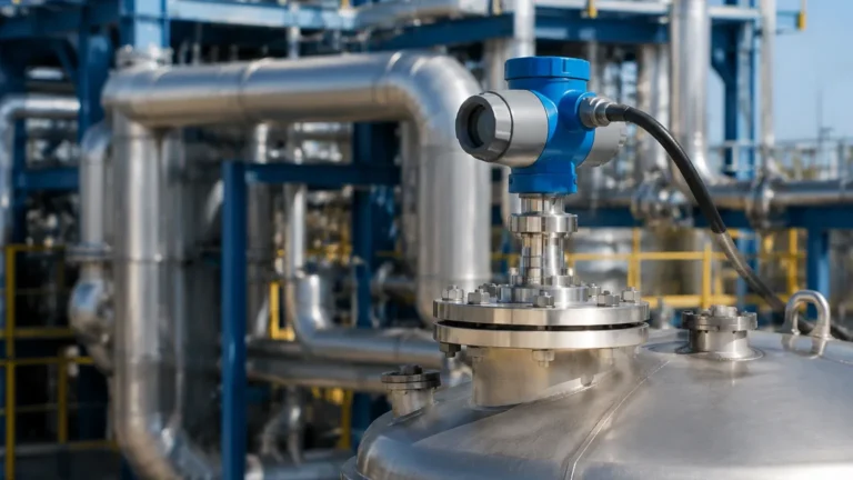
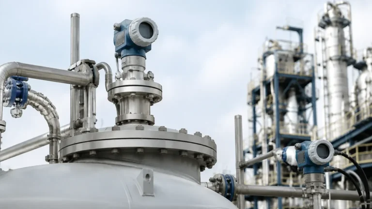
Guided Radar Level Transmitter Vega
Guided Radar Level Transmitter Vega: Engineering Principles and Industrial Selection Guide
In the field of industrial process automation, precise level measurement is critical for operational safety, inventory management, and process efficiency. Among the various technologies available, Guided Wave Radar (GWR) has emerged as a preferred solution for challenging environments involving foam, turbulence, or complex tank geometries. This guide examines the engineering principles, selection criteria, and installation requirements for GWR technology, referencing industry standards such as the guided radar level transmitter vega to provide a technical benchmark for procurement and system design.
Understanding the Principles of Guided Wave Radar (GWR)
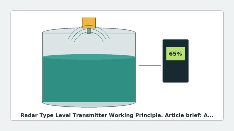
Guided Wave Radar technology is based on the principle of Time Domain Reflectometry (TDR). Unlike non-contact Radar Level Meters that transmit electromagnetic pulses through the air, a GWR transmitter directs low-energy microwave pulses along a physical conductor (the probe).
The TDR Measurement Process
1. Pulse Emission: The transmitter electronics generate a high-frequency electromagnetic pulse that travels down the probe at the speed of light.
2. Reflection: When the pulse encounters a medium with a different dielectric constant (εr) than the upper medium (usually air or vapor), a portion of the pulse energy is reflected back toward the transmitter.
3. Time-of-Flight Calculation: The device measures the time elapsed between the emission and the reception of the reflected signal. Since the speed of the pulse is constant, the distance to the product surface is calculated using the formula:
*Distance = (Speed of Light × Time of Flight) / 2.*
4. Level Conversion: The electronics subtract the measured distance from the total tank height (configured during commissioning) to determine the actual liquid or solid level.
Because the probe acts as a waveguide, the signal is concentrated and experiences significantly less attenuation compared to non-contact radar. This makes GWR exceptionally reliable in applications with low dielectric constants or where the surface is agitated.
Probe Selection and Engineering Configurations
Selecting the correct probe geometry is the most critical step in specifying a guided radar level transmitter vega or equivalent industrial instrument. The choice depends on the measurement range, the physical properties of the medium, and the presence of internal tank obstructions.
Comparison of Probe Types
| Probe Type | Maximum Range | Best Use Case | Limitations |
| :— | :— | :— | :— |
| Single Rod | Up to 6 m (20 ft) | Corrosive liquids, hygienic applications, viscous fluids. | Sensitive to nearby metal obstructions; requires larger clearance. |
| Single Cable | Up to 60 m (197 ft) | Deep tanks, silos, solids, or high-viscosity liquids. | Susceptible to swaying in high-turbulence; requires bottom anchoring. |
| Coaxial | Up to 6 m (20 ft) | Low dielectric liquids (εr < 1.4), turbulent surfaces, bypass pipes. | Prone to clogging with viscous or bridging materials. |
| Twin Cable/Rod | Up to 30 m (98 ft) | Long-range measurements of liquids with moderate dielectric constants. | Difficult to clean; prone to buildup between conductors. |
Material Considerations
Standard probes are typically manufactured from 316L stainless steel. For highly corrosive environments involving concentrated acids or chlorides, manufacturers like Welk offer probes coated with PTFE (Polytetrafluoroethylene) or constructed from exotic alloys such as Hastelloy C276.
Guided Radar Level Transmitter Vega: Industry Context and Performance Standards
When engineers discuss a guided radar level transmitter vega, they are often referring to the high standards of signal processing and reliability associated with the VEGAFLEX series. These instruments have set the bar for the industry by offering advanced "Echo Discovery" algorithms that can distinguish between the true level reflection and false echoes caused by tank internals.
For international buyers and plant managers, understanding these benchmarks is essential. Modern GWR transmitters must provide:
* High Pressure/Temperature Resistance: Capabilities reaching up to 400 bar (5,800 psi) and 450°C (842°F).
* Interface Measurement: The ability to measure both the total level and the interface level between two immiscible liquids (e.g., oil and water) simultaneously.
* SIL Certification: Compliance with Safety Integrity Level (SIL2/3) for use in critical overfill protection systems.
Installation Requirements and Geometric Constraints
To ensure the accuracy of Radar Level Meters using guided wave technology, specific installation geometry must be followed. Failure to adhere to these constraints can result in signal interference or "dead zones."
1. Distance from Tank Walls
For single rod or cable probes, the probe must be installed at a minimum distance from the tank wall to prevent signal interference. As a general rule, maintain a clearance of at least 300 mm (12 in). If the tank is non-metallic (plastic or fiberglass), a metal launch plate or flange must be used to provide a reference ground.
2. Nozzle Geometry
The height and diameter of the mounting nozzle significantly affect the signal. The nozzle diameter should be as large as possible, and the nozzle height should be kept to a minimum. If a long nozzle is unavoidable, a coaxial probe or a probe with a dedicated "inactive" section at the top may be required to avoid false reflections from the nozzle's bottom edge.
3. Obstructions and Agitators
While GWR is more resistant to obstructions than non-contact radar, the probe should still be positioned away from heating coils, ladders, and agitator blades. If an agitator is present, the probe must be secured at the bottom or housed within a bypass pipe or stilling well to prevent mechanical damage from fluid forces.
Overcoming Application Challenges: Foam, Turbulence, and Low Dielectrics
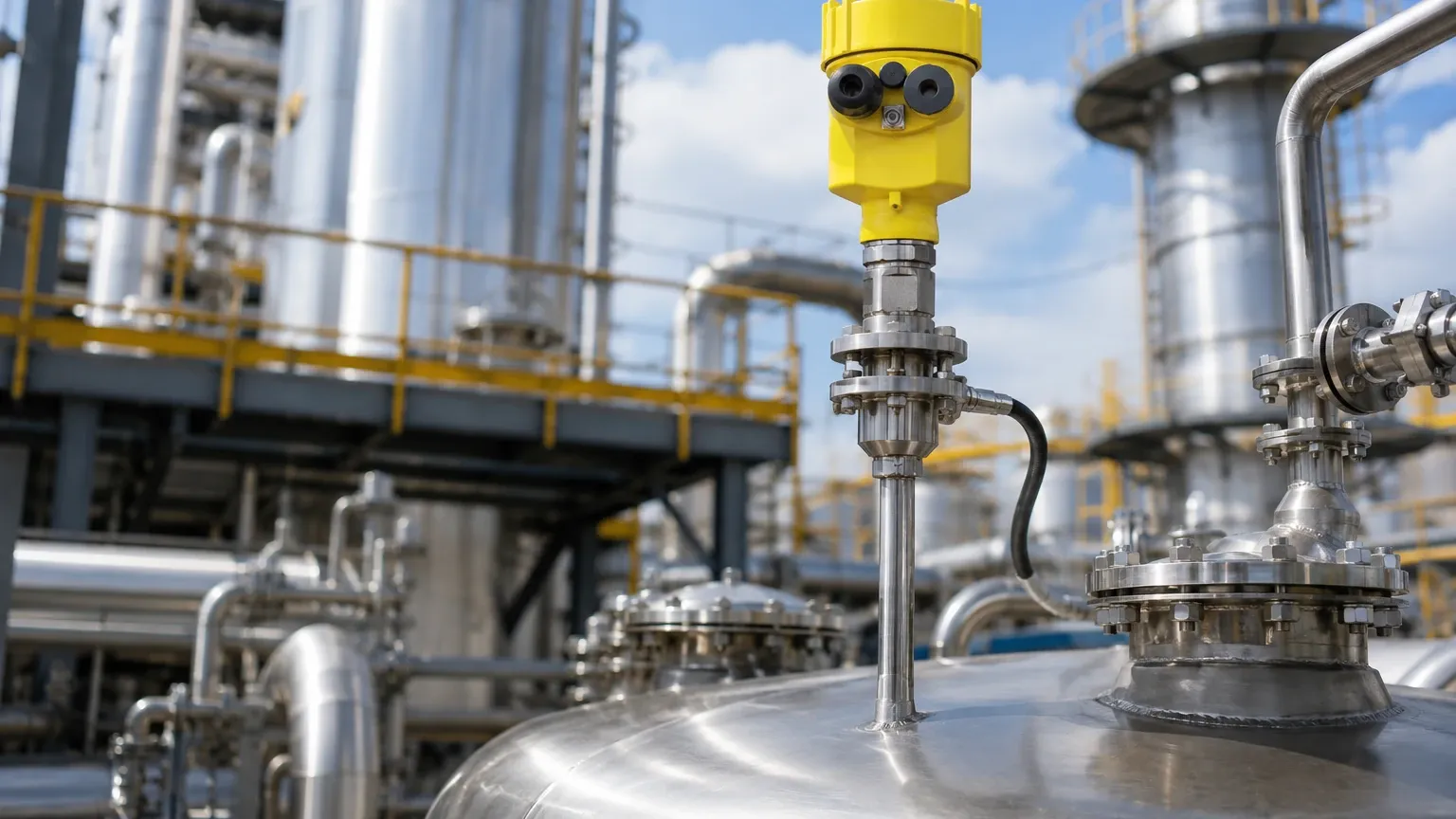
One of the primary advantages of a guided radar level transmitter vega-style device is its performance in difficult process conditions.
* Foam: In many chemical processes, foam can absorb or scatter non-contact radar signals. GWR pulses travel through most foams to reach the liquid surface. However, if the foam is extremely dense and conductive (e.g., certain soaps), it may produce its own reflection. Engineers must analyze the foam type to determine if GWR is the optimal choice.
* Turbulence: Rapidly changing levels or vortexes can cause signal loss in ultrasonic or non-contact radar sensors. The physical probe of a GWR transmitter keeps the signal path stable, ensuring continuous measurement even during aggressive mixing.
* Low Dielectric Constants: Hydrocarbons like LPG or solvents often have dielectric constants below 2.0. Standard radar may struggle to detect these surfaces. By using a coaxial probe, the electromagnetic field is confined within the tube, maximizing signal strength and allowing for the measurement of fluids with εr as low as 1.4.
Comparison: Guided Wave vs. Non-Contact Radar Level Meters
While both technologies utilize microwaves, their application envelopes differ significantly.
| Feature | Guided Wave Radar (GWR) | Non-Contact Radar |
| :— | :— | :— |
| Installation | Invasive (probe in medium) | Non-invasive (top-mounted) |
| Internal Obstructions | Less affected (signal guided) | Heavily affected (beam spread) |
| Maintenance | Higher (cleaning may be needed) | Lower (no contact) |
| Vapor/Dust | Unaffected | Can be affected by extreme density |
| Vacuum/Pressure | Excellent performance | Excellent performance |
| Maximum Range | Limited by probe length (60m) | Up to 120m+ |
For applications where the tank can be opened and a probe inserted, GWR is often the more robust choice for process vessels. For large-scale storage tanks or corrosive liquids where zero contact is mandatory, non-contact Radar Level Meters are preferred.
Maintenance and Troubleshooting for Industrial GWR Systems
Industrial GWR transmitters are designed for longevity, but certain conditions require routine checks:
* Build-up and Coating: While GWR is relatively immune to thin coatings, heavy buildup of conductive material (like metallic ores or wet salts) can bridge the probe to the tank wall, causing a short circuit and a false high-level reading.
* Probe Tension: For cable probes in tall silos, the tension should be checked periodically to ensure the probe has not become slack or entangled with internal structures.
* Seal Integrity: In high-pressure applications, the process seal (the barrier between the tank and the transmitter electronics) should be inspected for signs of leakage or degradation.
Frequently Asked Questions (FAQ)
Q: Can a guided radar level transmitter be used in plastic tanks?
A: Yes, but a metal flange or a large metal washer (launch plate) must be installed at the mounting point to provide a ground reference for the electromagnetic pulse.
Q: What is the "Upper Dead Zone"?
A: This is the area at the very top of the probe (near the flange) where measurement is not possible or accurate due to the pulse's transition from the electronics to the probe. It typically ranges from 50 mm to 200 mm (2 to 8 in).
Q: Can the probe be shortened in the field?
A: Most cable and rod probes can be cut to length during installation. However, the transmitter's configuration software must be updated to reflect the new probe length to maintain accuracy.
Q: Does the density of the liquid affect GWR measurement?
A: No. GWR measures the dielectric interface, not weight or pressure. Changes in liquid density, temperature, or pressure do not affect the accuracy of the level reading, provided the dielectric constant remains above the minimum threshold.
Conclusion
Specifying a guided radar level transmitter vega or a comparable Welk instrument requires a thorough understanding of the process environment and the physical properties of the medium. By selecting the appropriate probe geometry and adhering to strict installation guidelines, engineers can achieve highly accurate and maintenance-free level measurement in the most demanding industrial applications. For further technical specifications and product comparisons, consult the latest documentation on Radar Level Meters to ensure the selected solution meets the specific safety and operational requirements of your facility.