Guided Radar Level Transmitter Working Principle
Guided Radar Level Transmitter Working Principle: A Technical Engineering Guide
In the field of industrial process control, accurate level measurement is critical for safety, inventory management, and process efficiency. Among the various technologies available, Guided Wave Radar (GWR) has emerged as a highly reliable solution for challenging environments. This article provides a comprehensive technical analysis of the guided radar level transmitter working principle, its mechanical configurations, selection criteria, and practical installation requirements for engineering professionals.
1. Understanding the Guided Radar Level Transmitter Working Principle
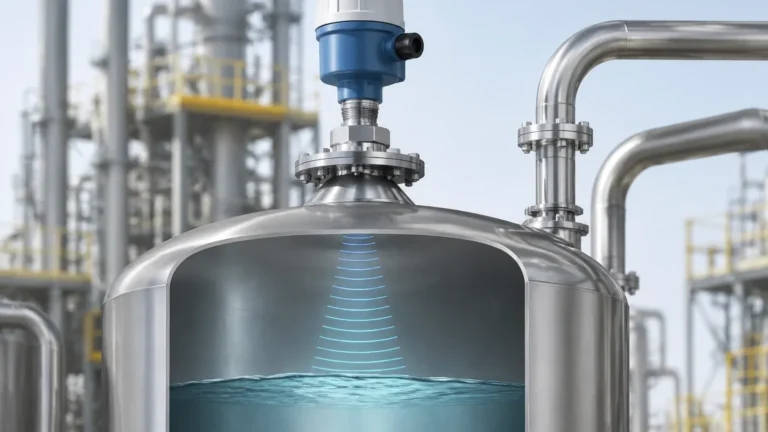
Guided Wave Radar technology is based on the principle of Time Domain Reflectometry (TDR). While non-contact Radar Level Meters emit electromagnetic pulses through the air, a guided radar transmitter directs these pulses along a physical waveguide (a probe).
The TDR Process
1. Pulse Emission: The transmitter's electronics generate low-energy microwave pulses (typically in the GHz range).
2. Propagation: These pulses travel down the probe at the speed of light. Because the pulse is confined to the waveguide, the energy remains concentrated, minimizing signal attenuation compared to open-air transmission.
3. Reflection: When the pulse encounters a change in the dielectric constant ($ε_r$) of the surrounding medium—specifically the interface between the gas phase (air or vapor) and the process media (liquid or solid)—a portion of the pulse energy is reflected back up the probe.
4. Signal Processing: The transmitter’s high-speed timing circuit measures the time of flight ($t$) between the pulse emission and the reception of the echo.
The distance ($D$) to the product surface is calculated using the formula:
$D = (c × t) / 2$
*Where $c$ is the speed of light and $t$ is the measured time.*
The Role of Dielectric Constant ($ε_r$)
The dielectric constant is the most critical factor in GWR performance. It determines how much energy is reflected. A medium with a high dielectric constant (e.g., water, $ε_r ≈ 80$) produces a very strong reflection. Conversely, media with low dielectric constants (e.g., hydrocarbons, $ε_r ≈ 1.9$ to $4.0$) reflect less energy, allowing some of the pulse to continue through the medium. This characteristic enables GWR to perform interface measurements, such as detecting the boundary between oil and water.
2. Probe Configurations and Their Applications
The choice of probe (waveguide) is determined by the physical properties of the media and the vessel geometry. There are three primary probe types utilized in industrial engineering.
Single Cable or Rod Probes
These consist of a single stainless steel cable or rod. They are the most versatile and easiest to clean. However, they are more sensitive to electromagnetic interference and the proximity of the tank wall or internal obstructions.
* Best for: Viscous liquids, slurries, and applications where coating or buildup is likely.
* Limitation: Requires a minimum distance from metal tank walls (typically 300 mm / 12 inches) to prevent signal interference.
Twin Cable or Rod Probes
Twin probes consist of two parallel conductors. The electromagnetic field is contained between the two rods/cables, making the signal stronger and less susceptible to external interference.
* Best for: Liquids with lower dielectric constants and longer measurement ranges where a coaxial probe is impractical.
* Limitation: Susceptible to bridging (material getting stuck between the probes), making them unsuitable for viscous or fouling liquids.
Coaxial Probes
Coaxial probes consist of a central rod inside an outer perforated tube. This design completely contains the electromagnetic field within the probe.
* Best for: Low dielectric liquids ($ε_r$ as low as 1.4), turbulent surfaces, and tanks with internal obstructions or narrow nozzles.
* Limitation: High risk of clogging. Not suitable for liquids that crystallize, contain solids, or have high viscosity.
Comparison Table: Probe Selection
| Feature | Single Rod/Cable | Twin Rod/Cable | Coaxial |
| :— | :— | :— | :— |
| Dielectric Range (ε_r) | > 1.9 | > 1.9 | > 1.4 |
| Viscous Media | Excellent | Poor | Not Recommended |
| Foam Resistance | Good | Fair | Excellent |
| Turbulence Resistance | Fair | Good | Excellent |
| Max Range (Approx.) | 30m – 60m | 30m | 6m |
3. Advantages of Guided Wave Radar
Understanding the guided radar level transmitter working principle reveals why this technology is preferred in specific industrial scenarios:
* Immunity to Vapor and Dust: Unlike ultrasonic sensors, GWR pulses are not affected by vacuum, high pressure, or heavy dust/vapor in the headspace.
* Surface Independence: GWR can measure levels accurately even in the presence of turbulence, foam, or boiling surfaces, as the probe guides the signal directly to the liquid interface.
* Interface Measurement: GWR is the industry standard for measuring the interface between two immiscible liquids (e.g., oil over water). The pulse reflects off the top layer and the second layer simultaneously.
* No Moving Parts: Compared to float-based systems or displacers, GWR requires minimal maintenance and is not prone to mechanical failure.
4. Installation Considerations and Constraints
To ensure the accuracy of a Radar Level Meter using guided waves, engineers must adhere to specific installation guidelines.
The "Dead Zone" (Blocking Distance)
Every GWR transmitter has an upper and lower dead zone.
* Upper Dead Zone: The area near the mounting flange where the transmitter cannot distinguish the surface reflection from the initial pulse. This usually ranges from 50 mm to 500 mm (2 to 20 inches) depending on the probe type and dielectric constant.
* Lower Dead Zone: The area at the tip of the probe where the signal may be distorted by the end of the waveguide.
Nozzle Geometry
The diameter and height of the mounting nozzle can impact signal quality. For single-rod probes, the nozzle should be as short and wide as possible to prevent "ringing" or false echoes from the nozzle wall.
Internal Obstructions
While the probe guides the signal, the electromagnetic field extends slightly beyond the physical probe (especially with single-rod designs). Proximity to agitators, ladders, or heating coils can create parasitic reflections. A minimum clearance must be maintained, or a coaxial probe should be used to shield the signal.
Probe Anchoring
In tall tanks or vessels with high agitation, cable probes must be anchored to the bottom to prevent excessive swaying. However, the anchor must be non-conductive or accounted for in the transmitter's software to avoid a permanent "bottom" error.

5. Application Risks and Limitations
Despite its robustness, GWR is not a universal solution. Engineers should be aware of the following risks:
1. Heavy Coating and Buildup: While GWR can handle some coating, significant buildup of conductive material (like metallic sludge) on the probe can attenuate the signal or cause the transmitter to "lock" on a false level.
2. Mechanical Stress: In high-viscosity liquids or high-flow environments, the lateral force on a rod probe can lead to bending or breakage. Cable probes are preferred for high-stress environments, provided they are properly weighted or anchored.
3. Low Dielectric Solids: Measuring dry solids (like plastic pellets or grain) with GWR is possible but requires careful probe selection. Low dielectric solids reflect very weak signals, and the angle of repose can affect the measurement.
6. Engineering Checklist for International Buyers
When procuring guided radar level transmitters for global projects, confirm the following technical specifications with the manufacturer:
* Process Media Properties: What is the minimum dielectric constant ($ε_r$) at the operating temperature? Does the media tend to coat or crystallize?
* Vessel Conditions: What are the maximum operating pressure (in bar or MPa) and temperature (in °C)? GWR probes are often rated up to 400 bar (5800 psi) and 450°C (842°F) for specialized high-temp/high-pressure models.
* Flange/Connection Standards: Ensure the mounting connection matches local standards (ANSI, DIN, or JIS).
* Output Requirements: Standard 4-20mA with HART is common, but Foundation Fieldbus, Profibus, or Modbus may be required for specific automation architectures.
* Certification: Does the environment require ATEX, IECEx, or SIL2/SIL3 functional safety ratings?
7. Frequently Asked Questions (FAQ)
Q: Can a guided radar transmitter measure level in a plastic tank?
A: Yes. However, since plastic is non-conductive, a single-rod probe may require a "ground plane" (a metal plate at the process connection) to launch the pulse effectively.
Q: Is GWR affected by changes in density?
A: No. Unlike hydrostatic pressure transmitters, GWR is a distance-based measurement and is unaffected by changes in the density or conductivity of the liquid.
Q: How does foam affect the measurement?
A: It depends on the foam's density and dielectric. Light, airy foam is usually transparent to the radar pulse, allowing measurement of the true liquid level. Dense, conductive foam may reflect the signal, providing a "foam level" reading. Coaxial probes are generally best for managing foam-related signal scattering.
Q: Can the probe be shortened in the field?
A: Most cable and rod probes can be cut to length on-site. However, the transmitter's configuration software must be updated with the new probe length to maintain accuracy.
Conclusion
The guided radar level transmitter working principle offers a precise and stable solution for industrial level measurement, particularly where traditional methods fail due to vapor, pressure, or surface turbulence. By selecting the appropriate probe geometry and accounting for the dielectric properties of the media, engineers can implement a measurement system that provides high reliability and low maintenance requirements across diverse process industries.
Download Guided Radar Level Transmitter Working Principle as a PDF