Coriolis Flow Sensor
Coriolis Flow Sensor
In the landscape of industrial process control, the ability to measure mass flow directly, rather than inferring it from volume and density, represents a significant advancement in precision. The Coriolis flow sensor has emerged as the gold standard for high-accuracy applications across the chemical, pharmaceutical, and oil and gas industries. Unlike volumetric flow meters, which are sensitive to changes in temperature, pressure, and fluid composition, a Coriolis flow sensor provides a direct measurement of mass, making it an indispensable tool for custody transfer and complex chemical blending.
For engineers and plant managers familiar with the robust level measurement solutions provided by manufacturers like Welk, integrating mass flow data with level data offers a comprehensive view of process efficiency. While level meters—such as radar or ultrasonic sensors—track the inventory within a vessel, the Coriolis flow sensor monitors the precise mass of material entering or exiting that vessel.
Understanding the Coriolis Measurement Principle
The operation of a Coriolis flow sensor is based on the principles of motion mechanics, specifically the Coriolis effect. To understand how this works in a practical industrial setting, one must look at the internal architecture of the device.
The Oscillation Mechanism
Inside the sensor housing are one or two measuring tubes. These tubes are forced to oscillate at their resonant frequency by an electromagnetic drive coil. When there is no fluid flowing through the tubes, they vibrate in a uniform, symmetrical manner. Both the inlet and outlet sides of the tube reach the peak of their vibration cycle at the exact same time.
The Coriolis Force
As fluid begins to flow through the vibrating tubes, the mass of the fluid introduces a new force. According to Newton’s Second Law of Motion, the fluid resists the acceleration and deceleration caused by the tube's vibration. This resistance creates a twisting effect on the tube.
On the inlet side, the fluid is moving toward the center of the vibration, resisting the upward motion of the tube. On the outlet side, the fluid is moving away from the center, resisting the downward motion. This results in a "phase shift" or a time delay between the vibration of the inlet and the outlet.
Direct Mass Measurement
This phase shift is directly proportional to the mass flow rate. Highly sensitive pick-off coils located on the inlet and outlet sections detect this shift. Because the measurement relies on the inertia of the mass itself, it is independent of the fluid’s viscosity, density, or flow profile (laminar or turbulent). For more information on how these sensors integrate into broader automation systems, you can visit the Main Page for technical resources.
Key Components and Design Variations
Coriolis flow sensors are engineered in several configurations to meet specific process requirements. The choice of design impacts sensitivity, pressure drop, and the ability to handle hygienic applications.
1. Bent Tube (U-Shape) Sensors
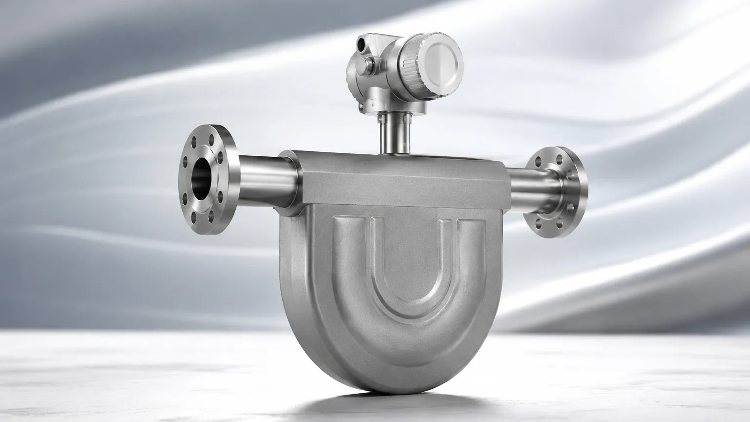
This is the most common design. The U-shape increases the length of the tube within a compact housing, which enhances the sensitivity of the phase shift measurement. These are ideal for low-flow applications where high precision is required. However, they can be more difficult to drain and may cause a higher pressure drop.
2. Straight Tube Sensors
Straight tube designs are preferred in the food and beverage and pharmaceutical industries. They are easier to clean (CIP/SIP compatible) and have a lower pressure drop. They are also less prone to trapping air or solids. However, because the phase shift is smaller in a straight tube, they require more sophisticated electronics to maintain accuracy.
3. Material Construction
The wetted parts of a Coriolis flow sensor must be compatible with the process media. Standard units often use 316L stainless steel, but for corrosive chemical applications, materials like Hastelloy C-22, Tantalum, or Titanium are utilized to ensure long-term reliability and safety.
Selection Criteria for Coriolis Flow Sensors
Choosing the right sensor requires an evaluation of the process fluid and the environmental conditions. The following table provides a general comparison of selection parameters for standard industrial applications.
| Parameter | Requirement/Range | Engineering Consideration |
| :— | :— | :— |
| Accuracy (Liquid) | ±0.05% to ±0.1% of rate | Critical for custody transfer and high-value blending. |
| Accuracy (Gas) | ±0.25% to ±0.5% of rate | Requires careful consideration of gas density and velocity. |
| Temperature Range | -200°C to +400°C | Specialized cryogenic or high-temp models may be needed. |
| Pressure Rating | Up to 400 bar (approx. 5800 psi) | Must match the piping class and safety factors. |
| Turndown Ratio | 10:1 to 100:1 | The range over which the sensor maintains stated accuracy. |
| Line Size | DN1 (1/25") to DN400 (16") | Selection depends on flow velocity and allowable pressure drop. |
Industrial Applications and Use Cases
Because the Coriolis flow sensor measures mass, density, and temperature simultaneously (multivariable measurement), it is used in a wide variety of demanding environments.
Chemical Processing
In chemical manufacturing, precise dosing of reactants is essential for product quality and safety. Coriolis sensors are used to measure aggressive chemicals where volumetric meters would fail due to changes in fluid viscosity or the presence of suspended solids.
Oil and Gas
Coriolis meters are the preferred choice for fiscal billing and custody transfer. Whether measuring crude oil, refined products, or Liquefied Natural Gas (LNG), the high accuracy and lack of moving parts reduce maintenance costs and eliminate the need for frequent recalibration compared to turbine meters.
Water and Wastewater Treatment
While Welk specializes in level measurement for tanks and basins, Coriolis sensors are employed in these facilities for the precise injection of chemicals like alum, polymers, and chlorine. Accurate mass flow ensures that water is treated effectively without wasting expensive chemical additives.
Installation and Maintenance Guidelines
Proper installation is critical for the performance of a Coriolis flow sensor. Because the device relies on internal vibration, external vibrations can introduce noise into the signal.
1. Mechanical Support
The sensor should be rigidly supported. It is recommended to install the sensor on a stable structure and use pipe supports on both the inlet and outlet sides to isolate the unit from piping vibrations. Do not use the sensor housing itself to support the weight of the adjacent piping.
2. Orientation
* For Liquids: The sensor should ideally be installed in a vertical pipe with the flow moving upward. This ensures the tubes remain full and prevents air bubbles from being trapped.
* For Gases: A horizontal installation with the tubes pointing upward (for U-tube designs) allows any condensed liquids to drain out of the tubes.
* For Slurries: Vertical installation with upward flow prevents the settling of solids within the measuring tubes.
3. Zero Calibration
After installation and under full-pipe, zero-flow conditions, a "zero trim" or zero calibration should be performed. This accounts for any stresses imposed on the sensor by the piping and ensures the base measurement is accurate.
Limitations and Challenges
While highly versatile, the Coriolis flow sensor is not a universal solution for every application. Engineers must be aware of the following limitations:
* Initial Cost: Coriolis sensors are generally more expensive than magnetic, vortex, or differential pressure flow meters. The investment is usually justified by the accuracy and reduced maintenance, but it may be prohibitive for simple water flow monitoring.
* Size and Weight: Larger line sizes (above 10 inches or 250mm) result in very heavy and bulky sensors, which can complicate installation and require significant structural support.
* Gas Entrainment: The presence of large amounts of undissolved gas in a liquid stream (slug flow) can dampen the tube vibration, leading to measurement errors or "stalling" of the sensor. Modern digital signal processing has improved performance in these conditions, but excessive gas remains a challenge.
* Pressure Drop: Depending on the tube design and flow velocity, the pressure drop across a Coriolis sensor can be higher than that of a full-bore magnetic flow meter.
Frequently Asked Questions (FAQ)
Q: Can a Coriolis flow sensor measure density?
A: Yes. The resonant frequency at which the tubes vibrate is directly related to the density of the fluid inside them. A heavier fluid results in a lower frequency, while a lighter fluid results in a higher frequency. This allows the sensor to provide real-time density data alongside mass flow.
Q: Does the sensor require straight pipe runs?
A: Generally, no. Unlike turbine or ultrasonic flow meters that require specific lengths of straight pipe to stabilize the flow profile, Coriolis sensors are unaffected by flow profile. They can be installed immediately after elbows or valves, though it is still good practice to avoid extreme turbulence directly at the inlet.
Q: How often should a Coriolis flow sensor be calibrated?
A: Because there are no moving parts to wear out, the calibration is extremely stable. Many industrial users perform a verification check annually, but full laboratory recalibration may only be necessary every 3 to 5 years, depending on the criticality of the application and local regulations.
Q: Can it measure the flow of non-conductive liquids?
A: Yes. Unlike magnetic flow meters which require the fluid to be conductive, Coriolis sensors work on any fluid with mass, including hydrocarbons, deionized water, and gases.
For professionals seeking to optimize their process measurement strategy, understanding the synergy between flow and level is essential. While a Coriolis flow sensor provides precision in the pipes, reliable level instruments ensure accuracy in the tanks. For a full range of industrial measurement solutions, including radar and ultrasonic systems, explore the technical specifications available on the Main Page.