E&h Mag Meter
E&h Mag Meter
Electromagnetic flowmeters, commonly referred to as mag meters, are the workhorse of volume flow measurement in industrial processes involving conductive liquids. Among the industry leaders, the E&H mag meter—specifically the Endress+Hauser Proline Promag series—is recognized for its reliability, modularity, and high degree of accuracy. These instruments are essential in sectors ranging from municipal water treatment to complex chemical processing, where precise flow data is critical for operational efficiency and safety.
Selecting the correct flow measurement technology requires a deep understanding of fluid dynamics and instrument construction. For engineers managing complex systems, integrating flow data with reliable level measurement is a standard requirement. To explore a comprehensive range of industrial measurement instruments that complement these flow solutions, professionals often consult the Main Page of specialized manufacturers to find integrated level and flow control options.
Understanding the Electromagnetic Measurement Principle
The operation of an E&H mag meter is based on Faraday’s Law of Electromagnetic Induction, which was formulated in 1831. The principle states that a conductor moving through a magnetic field induces an electrical voltage. In the context of a flowmeter, the conductive liquid acts as the conductor.
The Mathematical Foundation
The relationship is defined by the equation:
E = B · v · d
Where:
* E is the induced voltage (signal).
* B is the magnetic field strength generated by the meter’s coils.
* v is the average flow velocity of the liquid.
* d is the distance between the electrodes (typically the pipe diameter).
How it Works in Practice
Inside the sensor body, two electromagnetic coils are positioned to generate a constant magnetic field perpendicular to the flow direction. As the conductive fluid flows through the pipe, it cuts through this magnetic field, generating a voltage. This voltage is picked up by two electrodes mounted on the pipe wall. Because the magnetic field (B) and the electrode distance (d) are constant, the induced voltage (E) is directly proportional to the flow velocity (v). The transmitter then converts this voltage signal into a standardized output, such as 4-20 mA, pulse, or a digital protocol like HART or Modbus.
Key Components of an E&H Mag Meter
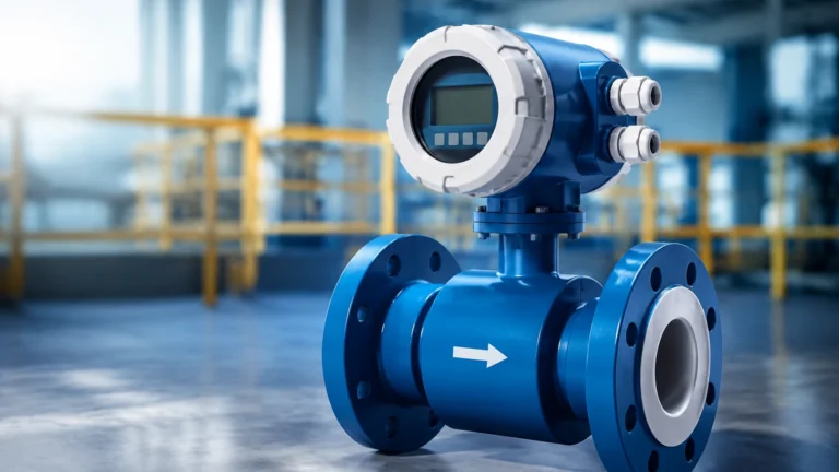
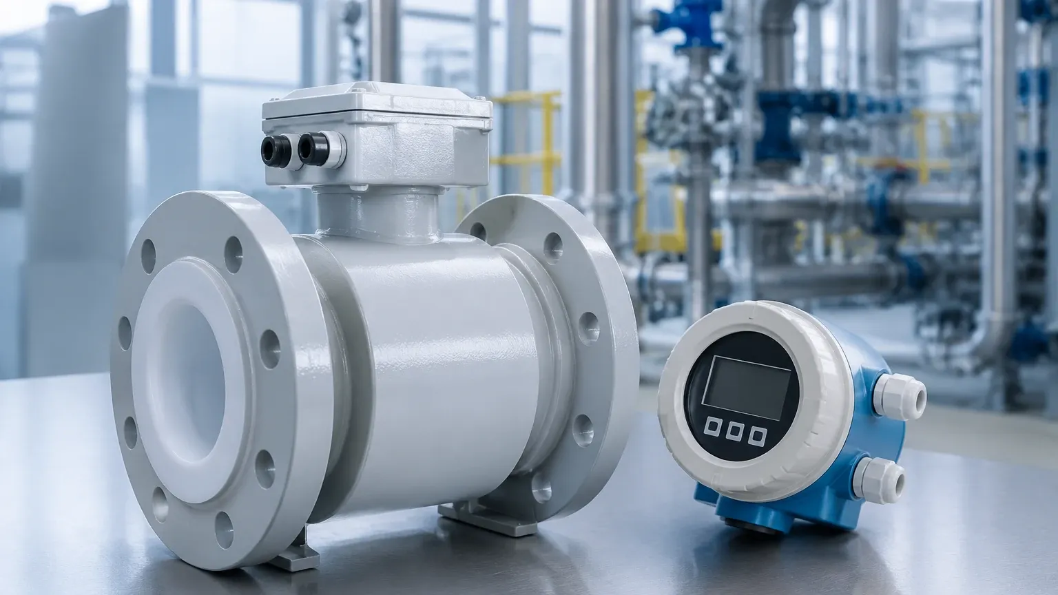
An E&H mag meter system consists of two primary parts: the sensor (the part installed in the pipeline) and the transmitter (the electronic "brain" that processes the signal).
1. The Sensor (Promag)
The sensor contains the flow tube, the insulating liner, the electromagnetic coils, and the electrodes. Because the measurement depends on the liquid being a conductor, the flow tube must be lined with a non-conductive material to prevent the induced voltage from short-circuiting through the metal pipe wall.
2. The Transmitter (Proline)
Endress+Hauser utilizes the Proline transmitter platform, which is categorized by its complexity and functionality:
* Proline 10: Designed for basic applications and ease of use, featuring a compact design and Bluetooth connectivity for commissioning.
* Proline 300/500: Advanced transmitters offering comprehensive diagnostics, including Heartbeat Technology for self-verification without process interruption. The 500 series features a remote transmitter design for difficult-to-access locations.
Selection Criteria for Industrial Applications
Choosing the right E&H mag meter depends on the chemical properties of the fluid, the physical environment, and the required accuracy. The Promag series is divided into several models, each optimized for specific industrial needs.
Promag W (The Water Specialist)
Primarily designed for the water and wastewater industry. It is available in large diameters (up to DN 3000 / 120 inches) and often features a "0 x DN" full-bore design, meaning it does not require straight pipe runs upstream or downstream to maintain accuracy.
Promag P (The Process Specialist)
Engineered for the chemical and process industries. It is built to withstand high temperatures (up to +180°C / +356°F) and corrosive fluids. It typically utilizes PFA or PTFE liners and specialized electrode materials like Tantalum or Platinum.
Promag H (The Hygienic Specialist)
Specifically for the food, beverage, and pharmaceutical industries. It features a stainless steel housing and hygienic connections that meet 3-A and EHEDG standards. The sensor is designed for CIP (Clean-in-Place) and SIP (Sterilization-in-Place) procedures.
Promag L (The Versatile Specialist)
A weight-optimized sensor with a lap-joint flange concept, making it easy to install in applications where weight and space are concerns, particularly in water distribution.
Technical Selection Table
| Feature | Promag W | Promag P | Promag H | Promag L |
| :— | :— | :— | :— | :— |
| Primary Industry | Water / Wastewater | Chemical / Oil & Gas | Food / Pharma | Water / Utilities |
| Nominal Diameter | DN 25 to 3000 | DN 15 to 600 | DN 2 to 150 | DN 25 to 300 |
| Liner Materials | Hard Rubber, Polyurethane | PTFE, PFA | PFA | Polyurethane |
| Max. Temperature | +80°C (176°F) | +180°C (356°F) | +150°C (302°F) | +50°C (122°F) |
| Accuracy | ±0.5% (std) / ±0.2% | ±0.5% (std) / ±0.2% | ±0.5% (std) / ±0.2% | ±0.5% |
Installation Guidelines for Optimal Accuracy
While mag meters are generally robust, improper installation is the leading cause of measurement error. To ensure the E&H mag meter performs to its specified accuracy, engineers must follow strict installation protocols.
1. Pipe Orientation and Filling
The pipe must always be completely full. If the pipe is only partially full, the meter will over-read flow velocity or fail to provide a stable reading. Vertical installation with upward flow is the preferred orientation, as this ensures a full pipe and prevents the accumulation of air bubbles.
2. Straight Pipe Runs (Inlet and Outlet)
Turbulence caused by valves, pumps, or elbows can distort the flow profile. Standard installations typically require an inlet run of 5 x DN (nominal diameter) and an outlet run of 2 x DN. However, certain E&H mag meter models (like the Promag W 0 x DN) use a multi-electrode design to compensate for turbulence, allowing for installation directly after bends.
3. Grounding and Potential Equalization
Since the induced voltage is often in the millivolt range, electrical noise can easily interfere with the signal. Proper grounding is essential. This involves connecting the sensor and the fluid to the same electrical potential. If the pipeline is plastic or lined, grounding rings must be installed between the flanges to ensure electrical contact with the fluid.
4. Electrode Orientation
In horizontal pipe runs, the electrode axis should be horizontal. This prevents the electrodes from being covered by sediment at the bottom of the pipe or by air bubbles at the top, both of which would interrupt the measurement signal.
Limitations and Common Challenges
Despite their versatility, E&H mag meters have specific limitations that must be addressed during the design phase.
* Conductivity Requirement: The liquid must have a minimum conductivity, typically $\ge 5 \mu S/cm$. This means mag meters cannot measure demineralized water, hydrocarbons (oils, fuels), or gases.
* Vacuum Sensitivity: Certain liners, such as PTFE, can collapse or peel away from the pipe wall under vacuum conditions. For applications involving vacuum, PFA or hard rubber liners with mechanical anchoring are required.
* Coating and Scaling: If the fluid contains substances that coat the electrodes (such as fats or minerals), the signal will eventually degrade. E&H addresses this with advanced diagnostics that monitor electrode integrity.
Complementary Technologies: Level and Flow Integration
In most industrial automation scenarios, flow measurement is only one part of the equation. For example, in a chemical dosing tank or a water reservoir, the flow rate measured by an E&H mag meter is often used in conjunction with level measurement to calculate mass balance or to prevent tank overfills.
Modern process control systems rely on a combination of radar level meters, ultrasonic sensors, and flowmeters to provide a complete picture of the process. For engineers looking to standardize their measurement infrastructure, sourcing high-quality level transmitters and switches is as vital as selecting the flowmeter itself. Reviewing the technical specifications on the Main Page can help in selecting the right hydrostatic or radar level instruments to work alongside a mag meter installation.
Frequently Asked Questions (FAQ)
Q: Can an E&H mag meter measure flow in both directions?
A: Yes, most modern mag meters are bi-directional. They can be configured to measure flow in both directions and provide separate totalizers for forward and reverse flow.
Q: What happens if the fluid conductivity drops below the threshold?
A: The meter will likely display an "Empty Pipe" alarm or provide highly erratic readings. If the conductivity is borderline, a specialized transmitter with high-impedance inputs may be required.
Q: How often does an E&H mag meter need calibration?
A: While the sensor has no moving parts and is very stable, many regulated industries (like water billing or pharmaceutical production) require annual or biennial verification. E&H’s Heartbeat Technology allows for in-situ verification, which can extend the intervals between formal lab calibrations.
Q: Can I use a mag meter for steam measurement?
A: No. Steam is a gas and does not have the required conductivity. For steam, vortex flowmeters or differential pressure meters are the appropriate technologies.
Q: Is it possible to install a mag meter in a plastic pipe?
A: Yes, but you must use grounding rings or electrodes specifically designed for potential equalization to ensure the fluid is properly grounded to the transmitter electronics.