Guided Radar Level Transmitter Rosemount
Guided Radar Level Transmitter Rosemount: An Engineering Guide to Guided Wave Radar Technology
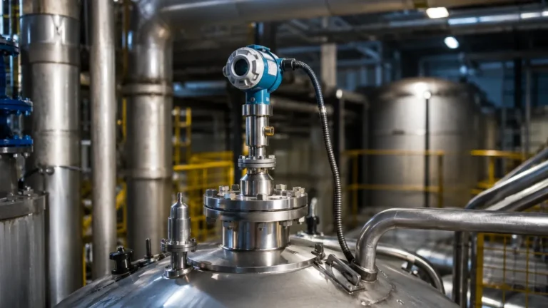
In the landscape of industrial process control, accurate level measurement is fundamental to safety, efficiency, and inventory management. Among the various technologies available, Guided Wave Radar (GWR) has emerged as one of the most versatile and reliable methods for both liquid and solid applications. While many engineers specifically search for the guided radar level transmitter Rosemount due to its established market presence, understanding the underlying physics, selection criteria, and installation nuances of GWR technology is essential for any technical buyer or plant operator.
This guide examines the principles of Guided Wave Radar, compares probe configurations, and provides the technical framework necessary to integrate high-performance Radar Level Meters into complex industrial environments.
1. The Principle of Guided Wave Radar (GWR) Measurement
Guided Wave Radar is based on the principle of Time Domain Reflectometry (TDR). Unlike non-contact radar, which broadcasts microwave pulses through the air, GWR utilizes a physical probe (a waveguide) to direct low-power microwave pulses from the transmitter head to the process medium.
The TDR Process
1. Pulse Emission: The transmitter electronics generate a low-energy electromagnetic pulse that travels down the probe at the speed of light.
2. Reflection: When the pulse reaches the surface of the product (liquid or solid), a portion of the pulse energy is reflected back toward the transmitter. This reflection occurs because of the change in the dielectric constant ($ε_r$) between the upper medium (usually air or vapor) and the process medium.
3. Signal Processing: The transmitter measures the time-of-flight—the interval between the emission of the pulse and the reception of the echo.
4. Calculation: Since the speed of the pulse is constant, the distance to the product surface is calculated as:
*Distance = (Speed of Light × Time of Flight) / 2*
The Importance of the Dielectric Constant ($ε_r$)
The dielectric constant of the material is the primary factor determining the strength of the reflection. Materials with high dielectric constants, such as water ($ε_r ≈ 80$), produce very strong reflections. Hydrocarbons and oils, which have lower dielectric constants ($ε_r ≈ 1.4$ to 5), reflect less energy. High-end systems, such as the guided radar level transmitter Rosemount 5300 series, utilize advanced signal processing to detect even these weak reflections in challenging low-dielectric applications.
2. Probe Selection and Configuration
The probe is the most critical component of a GWR system, as it is in direct contact with the process. Choosing the correct probe type depends on the medium's viscosity, the presence of internal tank obstructions, and the required measurement range.
Single Lead Probes
Single lead probes consist of a single rod or cable. They are the most common choice for industrial applications because they are less prone to media buildup.
* Applications: Viscous liquids, slurries, and applications where coating is likely.
* Limitation: They are more sensitive to electromagnetic interference from tank walls or internal structures. A minimum clearance (typically 300 mm or 12 inches) from the tank wall is required.
Twin Lead Probes
Twin lead probes utilize two parallel rods or cables. The dual-path design concentrates the energy between the leads, providing a stronger signal than single leads.
* Applications: Low dielectric liquids in larger tanks where wall interference is a concern.
* Limitation: They are highly susceptible to fouling. If material bridges the gap between the two leads, the transmitter will report a false high level.
Coaxial Probes
Coaxial probes consist of a central rod inside an outer pipe. This design functions like a high-frequency cable, completely containing the electromagnetic field within the probe.
* Applications: Extremely low dielectric liquids ($ε_r < 1.6$), highly turbulent surfaces, and tanks with dense internal obstructions.
* Limitation: Only suitable for clean, low-viscosity liquids. Any particulate matter or coating inside the tube will cause measurement failure.
| Probe Type | Best For | Dielectric Range ($ε_r$) | Resistance to Coating |
| :— | :— | :— | :— |
| Single Rod/Cable | General purpose, viscous fluids | > 1.9 | High |
| Twin Rod/Cable | Low dielectric, non-coating | > 1.5 | Low |
| Coaxial | Clean liquids, turbulence, bypass | > 1.2 | Very Low |
3. Comparing GWR and Non-Contact Radar
While both technologies fall under the umbrella of Radar Level Meters, they serve different operational needs. Understanding these differences is vital when considering a guided radar level transmitter Rosemount versus a non-contact equivalent.
Advantages of Guided Wave Radar
* Immunity to Vapor and Dust: Because the signal is guided, it is not scattered by heavy dust, steam, or foam on the surface of the liquid.
* Interface Measurement: GWR is the industry standard for measuring the interface between two liquids (e.g., oil over water). The pulse passes through the upper low-dielectric layer and reflects off the lower high-dielectric layer.
* Vacuum and High Pressure: GWR performs exceptionally well in vacuum conditions or high-pressure saturated steam, where the speed of light in air might otherwise fluctuate.
Advantages of Non-Contact Radar
* No Moving Parts/No Contact: Ideal for highly corrosive or abrasive materials that would degrade a physical probe.
* Ease of Maintenance: Since the sensor never touches the medium, there is no risk of probe breakage or the need for frequent cleaning.
4. Engineering Installation Considerations
To ensure the accuracy of a guided radar level transmitter, engineers must adhere to specific installation geometry. Failure to do so often results in "ghost echoes" or signal loss.
Nozzle Geometry
The nozzle height and diameter significantly impact the signal. For single lead probes, the nozzle should be as short and wide as possible to prevent the pulse from reflecting off the nozzle's internal edge before reaching the tank. If a long nozzle is unavoidable, a coaxial probe or a dedicated "nozzle compensation" software setting is required.
Obstructions and Clearances
* Dead Zones: Every GWR transmitter has an Upper Blocking Distance (Top Dead Zone) and a Lower Dead Zone. Measurement is not possible in these areas. Typically, the upper dead zone ranges from 100 mm to 500 mm (4 to 20 inches) depending on the probe and dielectric constant.
* Internal Obstacles: Probes must be installed away from agitators, heating coils, and ladders. For single lead probes, a rule of thumb is to maintain a distance of at least 300 mm (12 inches) from any metal object.
Mounting in Bypass Chambers
In many oil and gas applications, GWR transmitters are mounted in external bypass chambers (cages). This isolates the sensor from turbulence and allows for maintenance without depressurizing the main vessel. When using a bypass chamber, a coaxial probe or a single rod with centering disks is recommended to ensure the probe remains centered in the pipe.

5. Advanced Features in Modern Transmitters
When evaluating a guided radar level transmitter Rosemount, several advanced features differentiate industrial-grade equipment from basic sensors:
* Direct Switch Technology: This increases the signal strength of the reflected pulse, allowing for measurement over longer distances (up to 50 meters or 164 feet) and in lower dielectric media.
* Signal Quality Metrics: Modern transmitters provide diagnostic data on the "health" of the echo. If the signal strength drops due to probe coating or foam, the system can trigger a predictive maintenance alert before the measurement is lost.
* Probe End Projection: In cases where the signal is lost due to an extremely low dielectric constant, some transmitters can use the reflection from the end of the probe to calculate the level based on the change in propagation speed through the medium.
6. Limitations and Application Risks
Despite its robustness, GWR is not a universal solution. Engineers should be aware of the following limitations:
1. Mechanical Stress: In tall silos or high-flow tanks, the lateral forces (pull loads) on a cable probe can be immense. If the pull load exceeds the probe's tensile strength, it may snap, potentially damaging downstream equipment like pumps.
2. Heavy Coating: While single lead probes handle coating better than others, extreme buildup of conductive material (like wet metallic dust) can short-circuit the signal to the tank wall.
3. Dielectric Shifts: If the dielectric constant of the medium changes significantly due to temperature or chemical composition changes, the accuracy of interface measurements may be affected, as the pulse velocity through the upper layer changes.
7. Frequently Asked Questions (FAQ)
Q: Can I cut a GWR probe to length in the field?
A: Yes, most cable and rod probes can be shortened in the field. However, the transmitter's configuration must be updated with the new probe length, and the lower dead zone may need recalibration.
Q: How does foam affect Guided Wave Radar?
A: GWR is generally more resistant to foam than non-contact radar. However, very dense, thick foam may still cause a signal reflection, leading the transmitter to read the top of the foam layer instead of the liquid level.
Q: Is GWR suitable for solids and powders?
A: Yes, GWR is excellent for solids with high pull loads, provided a heavy-duty cable probe is used. It is particularly effective in tall, narrow silos where non-contact radar signals might bounce off the walls.
Q: What is the maximum temperature and pressure for these transmitters?
A: High-performance models can handle temperatures up to 400°C (752°F) and pressures up to 400 bar (5800 psi) when equipped with specialized ceramic seals.
Conclusion
The selection of a guided radar level transmitter Rosemount or a comparable high-precision instrument depends on a thorough analysis of the process environment. By understanding the interaction between the probe geometry and the dielectric properties of the media, engineers can implement level measurement solutions that offer long-term stability and minimal maintenance. For those seeking a wider range of high-frequency measurement options, exploring various Radar Level Meters provides the flexibility needed to match technology to specific industrial challenges, from simple water storage to complex hydrocarbon processing.