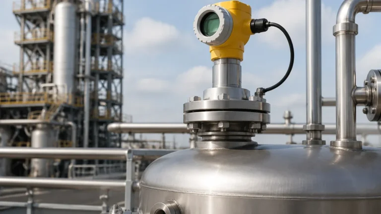
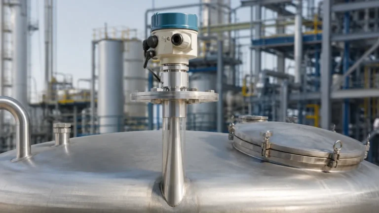
Radar Level Transmitter Part No. Sitrans Lr250 Siemens
Radar Level Transmitter Part No. Sitrans Lr250 Siemens: An Engineering Selection Guide
In the landscape of industrial process automation, selecting the correct instrumentation is critical for maintaining operational efficiency, safety, and inventory accuracy. Among the various technologies available for continuous level monitoring, high-frequency pulse radar has emerged as a gold standard for liquid and slurry applications. A prominent example in this category is the radar level transmitter part no. sitrans lr250 siemens. This guide provides a detailed technical analysis of the SITRANS LR250, its operating principles, configuration options, and installation requirements to assist engineers in making informed procurement decisions.
The Principle of 25 GHz Pulse Radar Technology
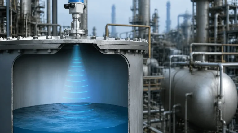
Before evaluating specific hardware, it is essential to understand the physics governing the measurement. The SITRANS LR250 operates on the principle of Pulse Radar, specifically utilizing a 25 GHz frequency. Unlike Frequency Modulated Continuous Wave (FMCW) radar, which emits a continuous signal with varying frequency, pulse radar sends out short microwave bursts toward the material surface.
Time-of-Flight (ToF) Measurement
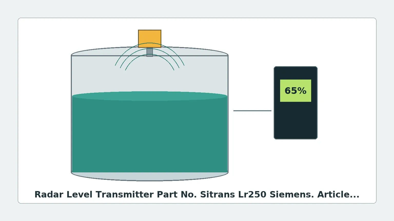
When the microwave pulse is emitted from the antenna, it travels at the speed of light. Upon reaching the surface of the medium (liquid or solid), a portion of the energy is reflected back toward the transmitter. The instrument measures the time elapsed between the emission of the pulse and the reception of the echo. Since the speed of light is constant, the distance is calculated using the formula:
Distance = (Speed of Light × Time of Flight) / 2
The "divided by two" accounts for the round-trip travel of the signal. The level of the material is then determined by subtracting the measured distance from the total height of the vessel.
The Advantage of 25 GHz Frequency
The choice of 25 GHz is significant. Lower frequency Radar Level Meters, such as those operating at 6 GHz, produce a wider beam angle, which increases the likelihood of signal interference from tank walls, agitators, or internal bracing. The 25 GHz frequency of the LR250 allows for a narrower beam and smaller antenna sizes, making it suitable for smaller nozzles and vessels with internal obstructions.
Decoding the Radar Level Transmitter Part No. Sitrans Lr250 Siemens
When ordering or specifying this equipment, the "Part No." is not a single static string but a configurable code (typically starting with 7ML5431) that defines the mechanical and electronic properties of the device. Understanding this configuration is vital for ensuring compatibility with the process environment.
Common Configuration Components
| Feature | Options/Variations | Engineering Significance |
| :— | :— | :— |
| Antenna Type | Horn, Encapsulated, Flanged Encapsulated | Determines chemical resistance and beam angle. |
| Process Connection | Threaded (G, NPT), Flanged (ANSI, DIN, JIS) | Must match the vessel's mounting port. |
| Communication | HART, PROFIBUS PA, FOUNDATION Fieldbus | Determines integration with the PLC/DCS system. |
| Enclosure | Aluminum, Stainless Steel | Impacts durability in corrosive or offshore environments. |
| Approvals | ATEX, IECEx, FM, CSA | Required for hazardous (Ex) zones. |
For instance, an engineer working with corrosive acids might specify a version with a PVDF encapsulated antenna to prevent chemical attack on the transmitter components. Conversely, a high-pressure oil application would require a stainless steel horn antenna with appropriate pressure ratings.
Selection Criteria for Industrial Applications
Choosing the radar level transmitter part no. sitrans lr250 siemens requires an assessment of the medium's physical properties and the vessel's geometry.
Dielectric Constant (εr)
The reflectivity of a material is determined by its dielectric constant. Materials with high dielectric constants (e.g., water-based liquids, εr > 10) reflect radar signals strongly. Hydrocarbons and oils often have low dielectric constants (εr < 3), which result in weaker echoes. The LR250 is designed to handle a wide range of εr values, but for extremely low dielectric materials, specialized horn antennas or larger diameters may be necessary to focus the energy.
Process Conditions
* Temperature: Standard models typically handle up to 200°C (392°F). High-temperature versions are required beyond this limit.
* Pressure: The transmitter can operate in vacuum or high-pressure environments (up to 40 bar / 580 psi depending on the flange and antenna type).
* Turbulence and Foam: While radar is generally superior to ultrasonic sensors in foamy conditions, heavy, dense foam can still absorb the signal. In such cases, a bypass pipe or stilling well may be recommended.
Installation Engineering and Constraints
Correct installation is the most critical factor in the performance of Radar Level Meters. Even the most advanced transmitter will fail if the signal path is obstructed or if the mounting geometry is incorrect.
Nozzle Design
The nozzle height and diameter must allow the radar beam to clear the bottom edge of the nozzle. If the nozzle is too long and narrow, "ringing" or parasitic reflections can occur within the pipe, masking the true level signal. As a rule of thumb, the antenna should extend at least 10 mm (0.4 inches) past the nozzle bottom into the tank.
The 1/10 Rule for Tank Placement
To avoid interference from the tank wall, the transmitter should be mounted at a distance from the wall equal to approximately 1/10 of the total tank height. For a 10-meter (33-foot) tank, the sensor should be placed 1 meter from the side wall. It should never be mounted in the center of a domed-top tank, as this can cause multiple reflections to converge at the sensor, creating a false high-level reading.
Avoiding Obstructions
Internal structures such as heating coils, ladders, and agitator blades are common sources of false echoes. The SITRANS LR250 includes "Auto False-Echo Suppression" software, which allows the user to map out these static obstructions. However, it is always best practice to mount the device where the beam has a clear, unobstructed path to the material surface.
Limitations of the SITRANS LR250
While highly versatile, the LR250 has specific limitations that engineers must acknowledge:
1. Dust and Solids: While the LR250 can measure some solids, it is primarily optimized for liquids and slurries. For heavy dust environments or large grain solids, a dedicated solids radar (like the SITRANS LR560) is often more appropriate.
2. Vapor and Condensation: Extreme steam or heavy condensation on the antenna can attenuate the signal. For these applications, an encapsulated antenna or a purging system is recommended to keep the lens clear.
3. Minimum Dielectric: For materials with a dielectric constant below 1.6, the reliability of the reflection decreases significantly unless a stilling well is used.
Maintenance and Troubleshooting
One of the primary benefits of non-contact radar is the lack of moving parts, which significantly reduces maintenance requirements compared to mechanical systems like float switches or displacers.
* Signal Quality Monitoring: Most modern transmitters provide a "Confidence" or "Signal-to-Noise Ratio" (SNR) value. A drop in confidence often indicates buildup on the antenna or a change in the material's properties.
* Cleaning: If the application involves sticky media, the antenna may require periodic cleaning. Choosing an encapsulated antenna (threaded or flanged) provides a flat surface that is easier to wipe down and less prone to material accumulation.
* Firmware Updates: Ensure the device is running the latest firmware to take advantage of improved signal processing algorithms and echo tracking.
Frequently Asked Questions (FAQ)
Q: Can the SITRANS LR250 be used in hazardous areas?
A: Yes, provided the specific part number includes the necessary approvals (e.g., ATEX, FM). It is available in Intrinsically Safe (IS) and Flameproof/Explosion-proof configurations.
Q: What is the maximum measurement range?
A: The LR250 generally supports ranges up to 20 meters (65.6 feet), though this depends on the antenna type and the dielectric constant of the material being measured.
Q: Is it possible to program the device without a handheld communicator?
A: Yes, the LR250 features a local user interface (LUI) with an infrared handheld programmer, or it can be configured via PC software using a HART modem or fieldbus interface.
Q: How does the LR250 handle agitators?
A: Through the use of its narrow 25 GHz beam and the Auto False-Echo Suppression feature, it can effectively ignore reflections from moving agitator blades, provided the blades do not completely block the signal path at all times.
Summary Table for Engineering Selection
| Parameter | Technical Specification |
| :— | :— |
| Technology | 25 GHz Pulse Radar |
| Accuracy | ± 3 mm (0.118 inches) |
| Range | Up to 20 m (65 ft) |
| Power Supply | 2-wire, 24V DC nominal |
| Output | 4-20 mA with HART, PROFIBUS PA, or FF |
| Min. Dielectric | 1.6 (un-stilled) |
| Housing Material | Aluminum or 316L Stainless Steel |
In conclusion, the radar level transmitter part no. sitrans lr250 siemens represents a robust solution for a wide array of liquid level measurement challenges. By understanding the nuances of the 25 GHz pulse technology and adhering to strict installation guidelines, industrial facilities can achieve high-precision monitoring even in complex process environments. For those exploring a broader range of options, comparing these specifications against other Radar Level Meters ensures that the selected instrument perfectly aligns with the specific demands of the application.
Download Radar Level Transmitter Part No. Sitrans Lr250 Siemens as a PDF