Termowell
Termowell
In industrial process control, the accurate measurement of temperature is as fundamental as the measurement of pressure, flow, and level. However, temperature sensors such as Resistance Temperature Detectors (RTDs) and thermocouples are often fragile and susceptible to damage from high pressures, corrosive chemicals, and high-velocity fluid flows. To protect these sensitive instruments while ensuring accurate thermal data, engineers utilize a termowell (thermowell).
A termowell is a cylindrical pressure-tight fitting used to protect temperature sensors installed in industrial processes. It acts as a barrier between the process media and the sensing element, allowing for the sensor to be removed or replaced without depressurizing the system or emptying the vessel. While Welk specializes in advanced level measurement technologies, such as radar and ultrasonic sensors available on our Main Page, the integration of temperature data is often a prerequisite for high-precision level monitoring, particularly in density-sensitive applications.
Measurement Principles and Thermal Dynamics
The fundamental principle of a termowell is heat conduction. The termowell is inserted into the process stream, where it reaches thermal equilibrium with the fluid. The internal temperature sensor then measures the temperature of the termowell's inner wall.
For a termowell to provide an accurate reading, several thermal factors must be managed:
1. Conduction Error: Heat travels along the length of the termowell from the process to the ambient environment (or vice versa). If the insertion length is too short, the ambient temperature can influence the sensor, leading to "stem conduction error."
2. Response Time: Because the termowell adds a layer of material between the fluid and the sensor, there is an inherent time lag. The thickness of the wall and the thermal conductivity of the material determine how quickly the sensor reacts to process changes.
3. Convection and Radiation: In gas applications, radiation from hot surfaces or convection patterns within the well can affect accuracy. Thin-walled or tapered designs are often used to minimize these effects.
Classification by Construction and Mounting
Termowells are categorized by their physical shape and how they are attached to the process piping or vessel. Choosing the correct geometry is vital for both mechanical integrity and measurement speed.
Stem Geometry
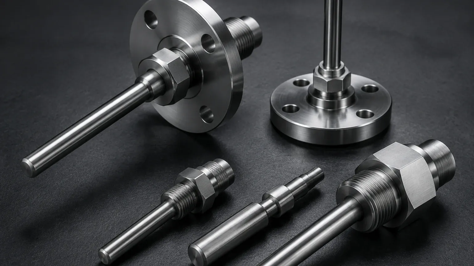
* Straight Termowells: The diameter is consistent along the entire insertion length. These are robust and easy to manufacture but have a slower response time due to the larger mass at the tip.
* Stepped Termowells: The diameter is reduced abruptly near the tip (usually from 19 mm to 12.5 mm, or 3/4" to 1/2"). This reduces the thermal mass, significantly improving response time while maintaining strength at the base.
* Tapered Termowells: The diameter gradually decreases from the base to the tip. This design provides the best balance between high structural strength (to resist vortex-induced vibrations) and a relatively fast response time.
Mounting Types
| Mounting Type | Connection Method | Typical Application | Advantages | Disadvantages |
| :— | :— | :— | :— | :— |
| Threaded | NPT or BSPT threads | Low-pressure, non-corrosive | Low cost, easy to install/replace | Potential for leaks at threads |
| Flanged | ANSI, DIN, or JIS flanges | High-pressure, hazardous, or corrosive media | Extremely secure, easy to clean | Higher cost and weight |
| Socket Weld | Welded into a socket | High-pressure, permanent installations | Leak-proof, high integrity | Difficult to replace or inspect |
| Weld-in | Directly welded to pipe | High-temperature steam, critical safety | Maximum pressure rating | Permanent; requires cutting to remove |
Material Selection for Industrial Environments
The choice of material for a termowell is dictated by the chemical compatibility with the process fluid, the operating temperature, and the potential for erosion.
* Stainless Steel (316/316L): The standard for most water treatment and mildly corrosive chemical applications. It offers a good balance of cost and durability.
* Hastelloy C-276: Used in highly aggressive environments involving acids or chlorides where stainless steel would suffer from pitting or stress corrosion cracking.
* Monel 400: Preferred for applications involving sea water or hydrofluoric acid.
* Tantalum: Often applied as a sleeve over a stainless steel base for extreme chemical resistance in pharmaceutical or specialized chemical processing.
* Ceramic (Alumina/Zirconia): Used primarily in high-temperature kilns or furnaces where metal alloys would melt or oxidize rapidly.
The Critical Role of Wake Frequency Calculations
One of the most common causes of termowell failure is not pressure or corrosion, but mechanical vibration. As fluid flows past a cylindrical termowell, it creates a phenomenon known as the Karman Vortex Street. This creates wake frequencies (vortices) that shed off the sides of the well.
If the frequency of these vortices matches the natural frequency of the termowell, resonance occurs. This leads to rapid metal fatigue and catastrophic snapping of the stem. To prevent this, engineers must perform calculations according to ASME PTC 19.3 TW. This standard evaluates:
1. Frequency Ratio: The ratio of the wake frequency to the natural frequency must typically be less than 0.8.
2. Static Stress: The ability of the well to withstand the constant pressure of the fluid.
3. Combined Stress: The total stress from fluid flow and pressure.
If a design fails the ASME PTC 19.3 TW test, the engineer must either shorten the insertion length, increase the root diameter, or use a "Scruton Well" (a design with helical fins to break up vortex formation).
Integration with Level Measurement Systems
While a termowell is a temperature accessory, it is indispensable for accurate level measurement in many industrial scenarios. At Welk, we provide various instruments on our Main Page that rely on temperature data for calibration and accuracy.
Density Compensation in Hydrostatic Level
Hydrostatic level transmitters measure the pressure exerted by a liquid column. The formula used is $P = \rho gh$ (Pressure = Density × Gravity × Height). Because liquid density ($\rho$) changes with temperature, a real-time temperature reading from a sensor inside a termowell allows the control system to adjust the density value, ensuring the calculated height ($h$) remains accurate despite thermal fluctuations.
Speed of Sound in Ultrasonic Level
Ultrasonic level sensors calculate distance based on the time it takes for a sound pulse to travel to the surface and back. The speed of sound in air (or a gas blanket) changes by approximately 0.6 m/s for every degree Celsius change. A termowell-mounted sensor provides the ambient or headspace temperature required to compensate for these changes, preventing errors that could exceed 5% of the total span.
Thermal Expansion in Magnetic Level Gauges
In high-temperature boiler applications, the physical expansion of the liquid and the chamber itself must be accounted for. Temperature monitoring ensures that the level indicated by a magnetic gauge or a magnetostrictive transmitter is corrected for the specific volume of the medium at operating conditions.
Installation and Maintenance Best Practices
Proper installation is critical to ensure that the termowell provides an accurate representation of the process temperature without becoming a point of failure.
1. Immersion Length (U-Length): For liquids, the rule of thumb is that the tip should be immersed at least 5 to 8 times the diameter of the termowell. For gases, the immersion should be 10 to 15 times the diameter to overcome stem conduction errors.
2. Orientation: In small-diameter pipes, termowells should be installed at an elbow (facing into the flow) or at an angle to ensure sufficient immersion length without obstructing the flow path.
3. Lagging Extension (T-Length): If the pipe or vessel is insulated, a lagging extension is required to extend the connection head beyond the insulation, preventing the electronics from overheating and allowing for easier access.
4. Heat Transfer Paste: In some applications, a thermal conductive paste is used inside the well to bridge the air gap between the sensor and the inner wall, decreasing response time. However, this is generally avoided in high-vibration environments as the paste can degrade or make sensor removal difficult.
Limitations and Risks
Despite their necessity, termowells introduce certain limitations to a process loop:
* Measurement Lag: In fast-moving thermal transients, the termowell may cause the control system to react too slowly. In these cases, direct-immersion sensors (without wells) might be used, though this sacrifices maintainability.
* Erosion: In slurries or high-velocity steam, the leading edge of the termowell can thin over time. Regular thickness testing or the use of Stellite coatings is recommended.
* Plugging: In viscous or "dirty" fluids, material can build up around the termowell, insulating it from the actual process temperature and causing significant measurement drift.
Frequently Asked Questions (FAQ)
Q: How do I choose between a tapered and a straight termowell?
A: Choose a tapered termowell for high-velocity applications (above 3 m/s for liquids) where vibration is a concern. Choose a straight termowell for low-velocity, low-pressure applications where cost-efficiency is a priority.
Q: What is the difference between a "U" length and a "T" length?
A: The "U" length is the immersion length—the distance from the bottom of the connection to the tip of the well. The "T" length is the lagging extension—the distance from the process connection to the sensor head, used to clear insulation.
Q: Can I use a termowell in a pipe smaller than 100 mm (4 inches)?
A: Yes, but you should install it at an elbow or use a pipe tee to expand the section where the termowell is inserted. This prevents the well from severely restricting the flow area.
Q: Why is my temperature reading lower than expected?
A: This is often due to stem conduction error. If the termowell is not immersed deeply enough into the fluid, the colder ambient air outside the tank pulls heat away from the sensor tip through the metal body of the well. Increasing the immersion length or insulating the external portion of the termowell usually resolves this.
For engineers designing comprehensive measurement loops, selecting the right termowell is as critical as selecting the primary level or pressure instrument. By ensuring mechanical stability and thermal accuracy, the termowell serves as the backbone of safe and efficient process monitoring. To explore our full range of level measurement solutions that integrate with these temperature systems, visit our Main Page.