Guided Wave Radar Level Transmitter Calculation
Guided Wave Radar Level Transmitter Calculation: A Technical Engineering Guide
In the field of industrial process control, accurate level measurement is fundamental to safety, efficiency, and inventory management. Among the various technologies available, Guided Wave Radar (GWR) has emerged as a highly reliable method for both liquid and solid applications. Unlike non-contact radar, GWR utilizes a physical probe to guide electromagnetic pulses, making it less susceptible to surface turbulence, foam, and tank geometry.
Understanding the specifics of guided wave radar level transmitter calculation is essential for engineers and procurement specialists to ensure the selected instrument performs within the required accuracy tolerances. This guide explores the underlying physics, the mathematical foundations of the measurement, and the practical selection criteria for industrial environments.
Understanding the Principle of Guided Wave Radar (GWR)
Guided Wave Radar is based on the principle of Time Domain Reflectometry (TDR). The instrument generates low-power microwave pulses (typically in the gigahertz range) that are transmitted along a waveguide—a metal probe or cable.
When these pulses reach the surface of the medium being measured (the interface between two materials with different dielectric constants), a portion of the pulse energy is reflected back to the transmitter. The electronics within the transmitter head measure the time of flight—the interval between the emission of the pulse and the reception of the echo.
Because electromagnetic waves travel at the speed of light, the transmitter must perform high-speed processing to convert these nanosecond intervals into distance. The primary advantage of Radar Level Meters using guided technology is that the signal is concentrated along the probe, resulting in a higher signal-to-noise ratio compared to non-contact radar, especially in narrow tanks or media with low dielectric constants.
The Fundamentals of Guided Wave Radar Level Transmitter Calculation
To derive a level reading from a time-of-flight measurement, the transmitter performs a series of internal calculations. The basic formula for distance ($D$) from the reference point (usually the process connection or flange) to the product surface is:
$$D = \frac{c \times t}{2 \times \sqrt{\epsilon_r}}$$
Where:
* $c$: The speed of light in a vacuum (approximately $299,792,458$ m/s).
* $t$: The measured time of flight (round trip).
* $\epsilon_r$: The relative permittivity (dielectric constant) of the medium through which the pulse travels (usually air or vapor, where $\epsilon_r \approx 1$).
Level Calculation
The actual level ($L$) of the material in the tank is then calculated by subtracting the measured distance ($D$) from the total tank height or the "zero point" ($Z$) configured in the device:
$$L = Z – D$$
The Role of the Dielectric Constant (εr)
The dielectric constant of the material being measured is the most critical factor in guided wave radar level transmitter calculation. It determines how much energy is reflected.
* High Dielectric Materials (e.g., Water, $\epsilon_r \approx 80$): These produce a very strong reflection, making measurement straightforward.
* Low Dielectric Materials (e.g., Hydrocarbons, $\epsilon_r \approx 1.9$ to $4$): These reflect only a small portion of the signal. In these cases, the pulse may continue through the liquid to the bottom of the probe. Transmitters often use "End-of-Probe" (EOP) algorithms to calculate level when the surface reflection is too weak to detect directly.
Selecting the Right Probe Configuration
The physical probe acts as the waveguide, and its geometry significantly impacts the signal strength and the calculation's reliability. Choosing the correct probe type is a prerequisite for accurate measurement.
| Probe Type | Best Application | Advantages | Limitations |
| :— | :— | :— | :— |
| Single Rod / Cable | Viscous liquids, slurries, solids | Easy to clean, resistant to coating | Sensitive to nearby tank walls and internal obstructions |
| Twin Rod / Cable | Long range, low dielectric liquids | Stronger signal than single rod | Prone to bridging/clogging between rods |
| Coaxial Probe | Low dielectric liquids, turbulent surfaces | Highest signal-to-noise ratio, immune to tank internals | Limited to clean, low-viscosity liquids; difficult to clean |
For most industrial applications involving Radar Level Meters, a single rod is preferred for its versatility, provided there is sufficient clearance from the tank wall (typically at least 300 mm or 12 inches).
Installation Constraints and Dead Zone Calculations
In practical engineering, the "measurable range" is not equal to the physical length of the probe. Every GWR transmitter has "Blocking Distances" or "Dead Zones" at the top and bottom of the probe where measurement is either impossible or inaccurate.
1. Upper Blocking Distance (Upper Dead Zone)
This is the area immediately below the process connection. In this region, the pulse is still stabilizing, and reflections from the mounting nozzle can interfere with the surface reflection.
* Calculation Impact: If the liquid level enters the upper dead zone, the transmitter may report a fixed value or a loss-of-echo error.
* Typical Value: 50 mm to 200 mm, depending on the probe type and dielectric constant.
2. Lower Blocking Distance (Lower Dead Zone)
This occurs at the tip of the probe. As the signal reaches the end of the rod, the reflection from the tip can overlap with the reflection from the liquid surface if the level is too low.
* Typical Value: 10 mm to 100 mm.
3. Nozzle Considerations
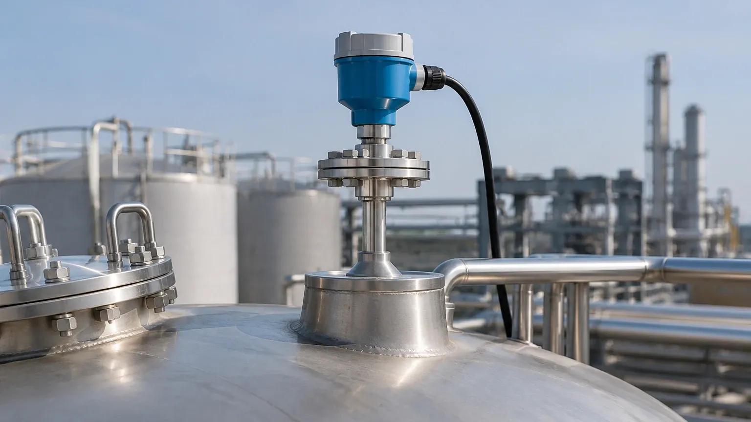
When mounting on a nozzle, the nozzle diameter ($d$) and height ($h$) must be considered. A tall, narrow nozzle can create parasitic reflections. Engineers should follow the $h \le d$ rule of thumb where possible, or ensure the transmitter has a "false signal suppression" feature to map out nozzle interference.
Interface Measurement and Dielectric Considerations
One of the unique capabilities of GWR is measuring the interface between two liquids (e.g., oil over water). This requires a specific set of calculations.
For an interface measurement to be successful:
1. The upper medium must have a lower dielectric constant than the lower medium.
2. The upper medium's dielectric constant must be known and relatively constant.
3. The upper layer must be thick enough (usually $>100$ mm) for the transmitter to distinguish between the two reflections.
The transmitter calculates the distance to the upper surface ($D_1$) using the standard TDR formula. It then calculates the distance to the interface ($D_2$) by accounting for the slower speed of the pulse as it travels through the upper liquid layer:
$$v_{upper} = \frac{c}{\sqrt{\epsilon_{r,upper}}}$$
Because $\epsilon_{r,upper} > 1$, the pulse slows down, and the transmitter must compensate for this "refraction" effect to accurately locate the interface.
Practical Application Limitations and Risks
While GWR is robust, certain factors can introduce errors into the guided wave radar level transmitter calculation:
* Build-up and Coating: While single-rod probes handle coating better than others, excessive conductive build-up can cause signal attenuation or "ghost" levels. If the medium is prone to crystallization, periodic cleaning or the use of a PTFE-coated probe is recommended.
* Vapor Space Composition: In high-pressure steam applications (e.g., boiler drum level), the dielectric constant of the vapor space increases significantly ($\epsilon_r > 1$). This slows the pulse and causes the transmitter to report a level lower than the actual level. High-end GWR units include "Gas Phase Compensation" using a reference reflector to correct this error in real-time.
* Probe Kinking: For cable-style probes, any kinks or sharp bends will create impedance changes that the transmitter may misinterpret as a surface level.
Selection Checklist for International Buyers
When specifying Radar Level Meters for industrial projects, ensure the following data points are confirmed with the manufacturer:
1. Process Media Dielectric Constant: Is it above the minimum threshold for the selected probe?
2. Temperature and Pressure: Does the process connection and seal material (e.g., Viton, Kalrez, Ceramic) match the environment?
3. Probe Length ($L$): Measured from the gasket face to the tip. Does it account for the bottom dead zone?
4. Output Protocol: 4-20mA HART is standard, but Foundation Fieldbus or Modbus may be required for integration into modern DCS/PLC systems.
5. Hazardous Area Certifications: Ensure ATEX, IECEx, or SIL2/3 requirements are met for chemical and oil/gas applications.
Frequently Asked Questions (FAQs)
Q: Can GWR measure levels in plastic tanks?
A: Yes. However, since plastic tanks do not provide a ground plane, GWR transmitters usually require a dual-rod probe or a special mounting plate to ensure signal stability.
Q: How does foam affect the measurement?
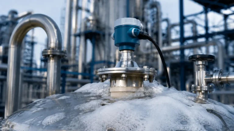
A: It depends on the foam's density and dielectric properties. Light, airy foam is usually transparent to the radar pulse, allowing measurement of the liquid beneath. Dense, wet foam may reflect the signal, causing the transmitter to measure the top of the foam layer.
Q: Is a guided wave radar affected by vacuum?
A: No. Since electromagnetic waves do not require a medium to travel, GWR is perfectly suited for vacuum applications. The calculation remains $D = (c \times t) / 2$ because $\epsilon_r$ of a vacuum is exactly 1.
Q: What is the maximum length for a guided wave radar probe?
A: Cable probes can typically extend up to 60 meters (approx. 197 feet), while rigid rod probes are usually limited to 6 meters (approx. 20 feet) due to shipping and installation constraints.
By meticulously applying the principles of guided wave radar level transmitter calculation and adhering to installation best practices, engineers can achieve sub-millimeter precision in even the most challenging industrial environments. For complex applications involving high-pressure steam or low-dielectric hydrocarbons, consulting with a technical specialist is recommended to ensure the probe geometry and signal processing algorithms are optimized for the specific process conditions.
Download Guided Wave Radar Level Transmitter Calculation as a PDF