Radar Level Transmitter Foam
Radar Level Transmitter Foam: Engineering Guide for Industrial Applications
In industrial process control, accurate level measurement is critical for safety, efficiency, and inventory management. However, the presence of foam on the surface of a liquid is one of the most persistent challenges for instrumentation engineers. Selecting the correct radar level transmitter foam solution requires a deep understanding of how electromagnetic waves interact with multi-phase interfaces.
This guide explores the technical principles of radar measurement in foaming environments, compares different technologies, and provides practical selection criteria for international buyers and plant engineers using Radar Level Meters.
1. Measurement Principles: How Radar Interacts with Foam
Radar level measurement operates on the Time of Flight (ToF) principle. The device emits high-frequency electromagnetic pulses (Pulse Radar) or a continuous wave with a varying frequency (FMCW – Frequency Modulated Continuous Wave). These waves travel at the speed of light, reflect off the surface of the medium, and return to the sensor. The distance is calculated based on the time delay or frequency shift.
The Role of the Dielectric Constant (εr)
The strength of the reflected signal depends primarily on the dielectric constant of the material. A high dielectric constant (e.g., water, εr ≈ 80) reflects most of the signal, while a low dielectric constant (e.g., hydrocarbons, εr < 2) allows much of the signal to penetrate or be absorbed.
Foam is a complex mixture of liquid and gas. Its impact on a radar signal is determined by:
* Dielectric properties of the base liquid: Aqueous foams are more reflective than oil-based foams.
* Foam Density: Denser foam contains more liquid, which increases its dielectric constant and its ability to reflect or attenuate signals.
* Bubble Size: If the bubble size is comparable to the wavelength of the radar signal, scattering occurs, significantly reducing the return signal strength.
2. Characterizing Foam Types in Industrial Processes
Before selecting a radar level transmitter foam configuration, it is essential to categorize the foam present in the vessel. Foam generally falls into two categories regarding its interaction with radar waves:
Dry, Light Foam
Dry foam consists of large bubbles with very low liquid content. It has a low dielectric constant, making it nearly transparent to radar waves. In these cases, the radar signal passes through the foam and reflects off the actual liquid surface. Standard non-contact radar level meters are typically sufficient for these applications.
Wet, Dense, or Thick Foam
Wet foam contains a high percentage of liquid and small, tightly packed bubbles. This type of foam can either reflect the signal prematurely (leading to a false high-level reading) or absorb the electromagnetic energy entirely (leading to a "signal lost" error). This is common in fermentation tanks, chemical reactors, and wastewater aeration basins.
3. Technology Comparison: Non-Contact vs. Guided Wave Radar
When dealing with foam, two primary radar technologies are utilized: Non-contact (Free-space) Radar and Guided Wave Radar (GWR).
Non-Contact Radar (80 GHz vs. 26 GHz)
Non-contact radar is preferred for corrosive or hygienic applications where the sensor should not touch the medium.
* 80 GHz Radar: High-frequency 80 GHz transmitters offer a narrow beam angle (as small as 3°). This focus helps avoid internal tank obstructions but can be more sensitive to signal scattering by small bubbles. However, advanced signal processing algorithms in modern 80 GHz units can often distinguish between the foam layer and the liquid surface.
* 26 GHz Radar: Lower frequency radar has a longer wavelength, which can sometimes penetrate light foam layers more effectively than higher frequencies, though the beam is wider and requires larger nozzles.
Guided Wave Radar (GWR)
In GWR, the radar pulse is guided along a physical probe (rod or cable). This technology is often the most reliable for heavy foam because the energy is concentrated around the probe, providing a much higher signal-to-noise ratio. GWR can often detect the interface between the foam and the liquid, or at the very least, provide a stable reading through the foam layer due to the increased signal strength.
4. Selection Criteria for Radar Level Transmitter Foam
Choosing the right instrument involves balancing the physical properties of the foam with the tank geometry and process conditions.
| Feature | 26 GHz Non-Contact | 80 GHz Non-Contact | Guided Wave Radar (GWR) |
| :— | :— | :— | :— |
| Foam Penetration | Moderate | Low to Moderate | High |
| Best Foam Type | Light/Dry | Light/Dry | Heavy/Wet/Dense |
| Installation | Top-mounted, non-contact | Top-mounted, small nozzle | Contact probe required |
| Maintenance | Very Low | Very Low | Moderate (probe cleaning) |
| Beam Angle | 8° – 20° | 3° – 6° | N/A (Guided) |
| Max Range | Up to 30m | Up to 120m | Up to 75m |
Key Considerations for International Buyers:
1. Frequency Selection: If the foam is thick and consistent, a lower frequency or GWR is typically safer. If the tank has many internal obstructions, 80 GHz non-contact is superior for its narrow beam.
2. Signal Processing: Look for transmitters with "False Echo Suppression" and "Multi-echo Tracking." These software features allow the user to mask out the foam's reflection and lock onto the liquid surface reflection.
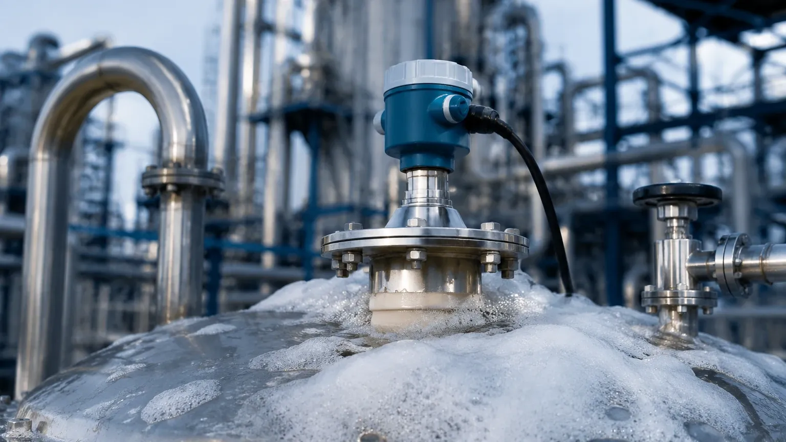
3. Antenna Design: For non-contact radar, a lens antenna or a PTFE-covered horn antenna is recommended to prevent foam from sticking to the sensor face and causing a signal blockage.
5. Installation and Engineering Best Practices
Proper installation can mitigate many of the issues caused by foam. Consider the following engineering guidelines:
* Nozzle Height and Diameter: Ensure the antenna extends slightly beyond the nozzle to prevent ringing or internal reflections. For foaming applications, larger nozzles are generally better as they allow for larger, more powerful antennas.
* Stilling Wells: If foam is extremely turbulent or thick, installing the radar inside a stilling well (a bypass pipe) can provide a foam-free surface for measurement. This is a common solution in the oil and gas industry.
* Purging Systems: In applications where foam might splash and dry on the antenna (crusting), a compressed air or water purging connection should be used to keep the antenna face clean.
* Mounting Position: Avoid mounting the transmitter directly over the liquid inlet where foam generation is most intense. Position the sensor in a calmer area of the tank.
6. Limitations and Application Risks
While radar is the most versatile level measurement technology, it is not infallible in foaming conditions. Engineers must be aware of the following limitations:
* Total Signal Absorption: In extreme cases, such as protein-based foams in the food industry or heavy chemical detergents, the foam can act as a perfect absorber. If no signal returns to the sensor, the transmitter will report an error.
* Dielectric Shift: If the foam's dielectric constant is very close to the liquid's, the radar may not be able to distinguish between the two, leading to a measurement of the top of the foam rather than the liquid.
* Crusting: If the foam dries and forms a hard crust on the antenna or GWR probe, the signal will be attenuated or reflected at the crust layer. Regular maintenance or purging is required in these scenarios.
7. Frequently Asked Questions (FAQ)
Q: Can a radar level transmitter see through foam?
A: It depends on the foam's density and moisture content. Radar can easily see through dry, large-cell foam. However, wet, dense foam will either reflect the signal or absorb it. Guided Wave Radar is generally better at "seeing through" or bypassing foam layers than non-contact radar.
Q: Is ultrasonic better than radar for foam?
A: Generally, no. Ultrasonic waves are sound waves (mechanical energy) which are easily absorbed and scattered by the air-pocket structure of foam. Radar (electromagnetic energy) is much more effective at penetrating foam layers.
Q: What is the best frequency for a radar level transmitter foam application?
A: There is no single "best" frequency. 80 GHz is excellent for avoiding tank obstructions and providing high precision, but 26 GHz or lower frequencies are sometimes less affected by the scattering caused by small bubbles in the foam.
Q: How does Guided Wave Radar (GWR) handle foam compared to non-contact?
A: GWR is more robust in heavy foam because the pulse is concentrated along the probe. This concentration allows the pulse to penetrate the foam layer more effectively. Even if the foam is dense, the GWR can often detect the change in dielectric constant at the liquid interface more clearly than a free-space radar.
8. Conclusion
Successful level measurement in foaming applications depends on matching the radar technology to the specific characteristics of the foam. For light, airy foams, 80 GHz non-contact Radar Level Meters offer the best combination of precision and ease of installation. For dense, wet foams that threaten signal integrity, Guided Wave Radar or the use of a stilling well remains the engineering standard.
When specifying a radar level transmitter foam solution, always provide the manufacturer with the liquid's dielectric constant, the expected foam thickness, and the bubble characteristics to ensure the selected instrument is configured with the appropriate power and signal processing capabilities.