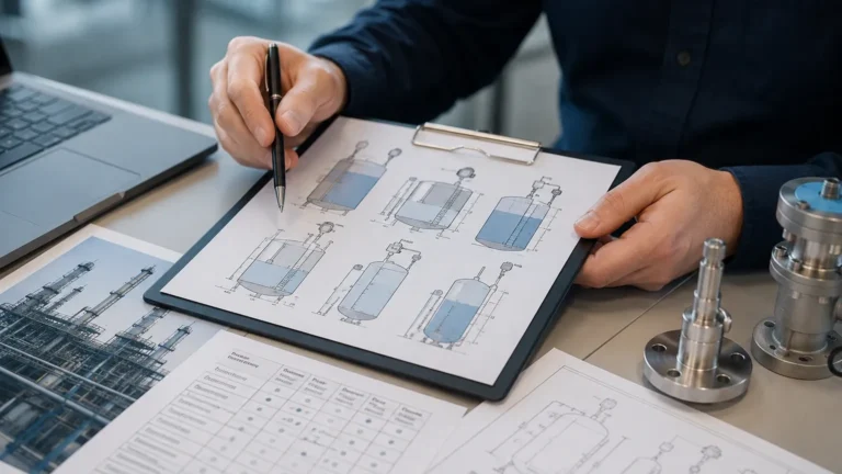
Level Measurement Instruments
Level Measurement Instruments
In the landscape of industrial automation, level measurement instruments serve as critical components for process control, inventory management, and safety assurance. Whether managing water treatment facilities, chemical processing plants, or oil and gas storage, the ability to accurately determine the volume or height of a substance within a vessel is fundamental to operational efficiency. Selecting the appropriate technology requires a deep understanding of measurement principles, media characteristics, and environmental constraints.
As a professional manufacturer, Welk provides a comprehensive range of level measurement instruments designed to meet the rigorous demands of global industries. This guide explores the core technologies currently available, offering engineering insights into their application and selection.
Measurement Principles and Technologies
Modern level measurement instruments utilize various physical principles to detect the surface of liquids, solids, or interfaces. Understanding these principles is the first step in ensuring a reliable installation.
Radar Level Measurement
Radar technology is widely considered the gold standard for high-accuracy applications. It is divided into two primary categories: Non-contact Radar and Guided Wave Radar (GWR).
* Non-contact Radar: These instruments emit high-frequency electromagnetic pulses (typically in the 26GHz or 80GHz range) toward the product surface. The pulses are reflected back to the sensor. By measuring the time-of-flight (ToF) or the frequency shift (FMCW – Frequency Modulated Continuous Wave), the instrument calculates the distance. Because electromagnetic waves do not require a medium for travel, they are unaffected by vacuum, high temperatures, or pressure changes.
* Guided Wave Radar (GWR): GWR instruments utilize a physical probe (cable or rod) to guide the microwave pulse to the surface. This method is particularly effective for low dielectric constant (dK) fluids and interface measurements (e.g., oil over water), as the probe concentrates the energy and reduces signal loss.
Ultrasonic Level Sensors
Ultrasonic sensors operate on the principle of sound wave reflection. The sensor emits an ultrasonic pulse that travels through the air, hits the target surface, and returns to the transducer. The distance is calculated based on the speed of sound. While cost-effective and easy to install, ultrasonic level measurement instruments are sensitive to air temperature fluctuations, heavy foam, and vacuum conditions, as sound requires a gaseous medium to propagate.
Hydrostatic Level Transmitters
Hydrostatic measurement is based on the relationship between the height of a liquid column and the pressure it exerts at the base of a tank. The formula $P = \rho \cdot g \cdot h$ (where $P$ is pressure, $\rho$ is density, $g$ is gravity, and $h$ is height) allows the transmitter to convert pressure readings into level data. These are typically submersible sensors or externally mounted pressure transducers. They are highly reliable for vented tanks but require compensation for vapor space pressure in sealed vessels.
Magnetic Level Gauges
Magnetic gauges provide a clear, visual indication of level without requiring power. They consist of a float containing a high-intensity magnet that moves inside a bypass chamber. As the float rises and falls with the liquid level, the magnet flips colored flaps or rollers on an external scale. These are ideal for high-pressure, high-temperature, or corrosive environments where electronic components might fail.
Level Switches
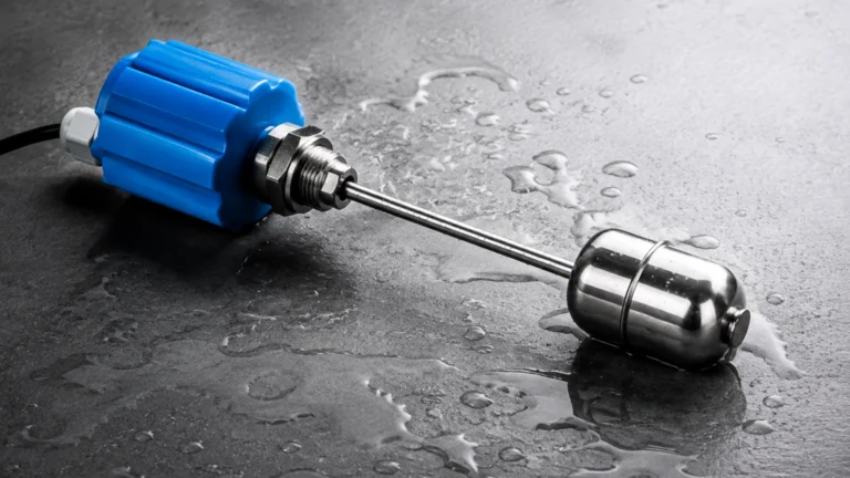
Unlike continuous transmitters, level switches are used for point-level detection. Common types include vibrating forks, float switches, and capacitive switches. They are essential for overfill protection (High-High) and pump dry-run prevention (Low-Low).
Practical Selection Table
Choosing between different level measurement instruments involves balancing performance requirements with budget and environmental factors. The following table provides a general comparison of common technologies.
| Technology | Typical Accuracy | Max Range (m) | Media Type | Key Advantage | Limitation |
| :— | :— | :— | :— | :— | :— |
| 80GHz Radar | ±1 mm | 120m | Liquid / Solid | High precision; small beam angle | Higher initial cost |
| Ultrasonic | ±0.25% of range | 15m – 30m | Liquid / Slurries | Non-contact; economical | Affected by foam/vapor |
| Hydrostatic | ±0.1% to 0.5% | 200m+ | Liquids | Simple; deep well capable | Sensitive to density changes |
| Guided Wave Radar | ±2 mm | 30m – 75m | Liquid / Interface | Stable in turbulence/steam | Probe subject to coating |
| Magnetic Gauge | Visual | 6m+ | Liquids | No power needed; robust | Mechanical moving parts |
Key Evaluation Criteria for Engineers
When specifying level measurement instruments for a project, several technical parameters must be confirmed to ensure the longevity of the device.
1. Media Characteristics: Is the fluid corrosive, viscous, or prone to crystallization? For corrosive media, PTFE or PVDF wetted parts are required. For solids, the dielectric constant and dust levels will determine if radar or ultrasonic is more suitable.
2. Process Conditions: Standard instruments typically handle up to 80°C and 2 bar. For extreme applications, such as steam boilers or cryogenic storage, specialized high-temperature (up to 450°C) and high-pressure (up to 400 bar) versions are necessary.
3. Vessel Geometry: Internal obstructions like agitators, heating coils, or baffles can create false echoes for non-contact sensors. In such cases, narrow-beam 80GHz radar or Guided Wave Radar is preferred to avoid interference.
4. Accuracy Requirements: Inventory custody transfer requires millimeter-level precision (radar), while simple pump control may only require the ±1% accuracy provided by hydrostatic or ultrasonic sensors.
For a detailed look at specific product specifications and technical datasheets, engineers can consult the Main Page to review product options and application support.
Installation Considerations and Best Practices
Even the most advanced level measurement instruments will fail to perform if installed incorrectly. Follow these engineering guidelines for optimal results:
* The Dead Zone (Blocking Distance): Every non-contact sensor has a "dead zone" near the transducer face where measurements cannot be taken. Ensure the maximum expected liquid level does not enter this zone, or use a nozzle extension to raise the sensor.
* Nozzle Design: The mounting nozzle should be as short and wide as possible to prevent signal interference from the nozzle walls. For radar, the antenna should ideally extend slightly past the bottom of the nozzle.
* Positioning: Avoid mounting the sensor in the center of a tank (which can cause multiple reflections) or directly above the filling inlet (where turbulence and falling material will disrupt the signal).
* Stilling Wells: In tanks with heavy agitation or foam, installing the sensor inside a stilling well or bypass pipe can provide a calm surface for more accurate readings.

Common Risks and Limitations
While modern technology has mitigated many issues, certain risks remain inherent to level measurement:
* Build-up and Coating: In wastewater or chemical mixing, material can accumulate on the sensor face or probe. While some radar units feature "build-up compensation," manual cleaning or the use of non-stick materials like PTFE is often necessary.
* Vapor and Gas Layers: Heavy steam or chemical vapors can change the speed of sound, significantly affecting ultrasonic accuracy. Radar is generally immune to this, but extremely high-pressure steam can slightly attenuate radar signals.
* Density Fluctuations: Hydrostatic sensors rely on a constant density. If the temperature of the liquid changes drastically or if different fluids are mixed, the level reading will drift unless a temperature-compensated system is used.
Frequently Asked Questions (FAQ)
Q: Can radar level meters measure solids like grain or cement?
A: Yes. However, solids often have a low dielectric constant and create sloped surfaces. High-frequency 80GHz radar is recommended because its narrow beam and high sensitivity can better handle the weak reflections from uneven solid surfaces.
Q: What is the benefit of a 2-wire vs. 4-wire instrument?
A: 2-wire instruments are loop-powered (4-20mA), meaning power and signal share the same pair of wires, simplifying installation. 4-wire instruments have separate power supplies, which is often necessary for power-intensive features like heated displays or high-power long-range transducers.
Q: How do I handle measurement in a tank with a heavy agitator?
A: Guided Wave Radar (GWR) is often the best choice because the signal follows the probe and is less affected by surface turbulence. Alternatively, a non-contact radar with a fast sampling rate and sophisticated software filtering can "mask" the agitator blades.
Q: Are ultrasonic sensors suitable for vacuum tanks?
A: No. Ultrasonic waves require a medium (air or gas) to travel. In a vacuum, there is no medium to carry the sound pulse, making the sensor inoperable. Radar is the correct choice for vacuum applications.
Conclusion
Selecting the right level measurement instruments is a balance of physics, chemistry, and mechanical engineering. By understanding the strengths and limitations of radar, ultrasonic, hydrostatic, and magnetic technologies, operators can ensure long-term reliability and safety. For customized OEM/ODM services or technical guidance on specific industrial automation applications, professional consultation is recommended to match the instrument to the unique demands of the process environment.