Fluidized Catalytic Cracking Unit
Fluidized Catalytic Cracking Unit
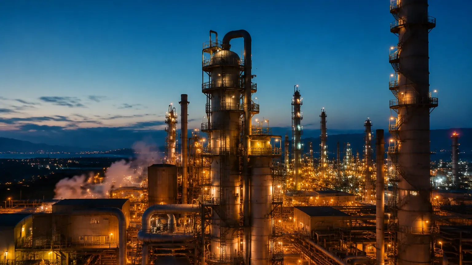
In the complex landscape of modern petroleum refining, the Fluidized Catalytic Cracking Unit (FCCU) stands as the primary conversion process for upgrading heavy atmospheric and vacuum gas oils into high-value products like gasoline, C3/C4 olefins, and cycle oils. As the "heart" of the refinery, the efficiency and safety of the FCCU are heavily dependent on precise process control, where level measurement plays a foundational role. Managing the interface between solid catalyst particles and hydrocarbon vapors requires a sophisticated understanding of fluid dynamics and specialized instrumentation capable of withstanding extreme temperatures and abrasive environments.
The Role of the Fluidized Catalytic Cracking Unit in Refining
The fundamental objective of a fluidized catalytic cracking unit is to break down complex, long-chain hydrocarbons into smaller molecules. This is achieved through a catalytic reaction at high temperatures, typically ranging from 500°C to 540°C (932°F to 1004°F) in the reactor. The process is unique because it utilizes a fine, powder-like catalyst that, when aerated with air or steam, behaves like a fluid. This "fluidized" state allows the catalyst to circulate continuously between the reactor, where cracking occurs, and the regenerator, where coke deposits are burned off the catalyst surface.
Level control within this loop is critical. In the reactor, the catalyst bed level must be maintained to ensure sufficient contact time between the feed and the catalyst. In the regenerator, level monitoring prevents catalyst loss and ensures the air distribution remains effective for combustion. If levels are not accurately managed, the refinery faces risks ranging from reduced product yield to catastrophic equipment damage caused by "catalyst carryover" into downstream fractionators.
Measurement Principles for FCCU Environments
Selecting instrumentation for a fluidized catalytic cracking unit requires an understanding of different physical principles, as no single technology fits every vessel in the unit. The environment is characterized by high turbulence, high temperatures (up to 760°C in the regenerator), and the presence of abrasive catalyst fines.
1. Radiometric (Nucleonic) Measurement
Radiometric level measurement is often considered the gold standard for the harshest sections of the FCCU. This principle involves a small gamma-ray source mounted on one side of the vessel and a sensitive detector on the opposite side. As the catalyst level rises, it attenuates the radiation reaching the detector. Because the system is mounted externally, it is not subject to the extreme heat or erosion inside the vessel. This makes it ideal for the reactor and regenerator catalyst beds.
2. Radar Level Measurement (FMCW)
Frequency Modulated Continuous Wave (FMCW) radar is frequently used in the fractionator section of the FCCU. The sensor emits a continuous signal with a changing frequency. The reflection from the liquid surface is compared to the emitted signal, and the frequency difference is used to calculate the distance. In the FCCU, high-frequency radar (80GHz) is preferred for its narrow beam angle, which helps avoid internal obstructions like baffles and agitators.
3. Differential Pressure (DP)
DP transmitters measure the hydrostatic head of the fluid or catalyst bed. By measuring the pressure difference between the bottom and the top of the vessel, the level can be inferred based on the known density of the medium. In a fluidized catalytic cracking unit, DP is commonly used in standpipes and catalyst transfer lines, though it requires constant purging with steam or nitrogen to prevent the pressure taps from plugging with catalyst powder.
Technical Selection Criteria
When evaluating level measurement solutions for an FCCU, engineers must prioritize reliability and longevity. For a broader look at available industrial technologies, professionals can consult the Main Page to review product options and application support. Key criteria for selection include:
* Temperature Resistance: Instruments in the regenerator section must withstand temperatures exceeding 700°C. If the sensor is wetted (in contact with the process), it must be constructed from specialized alloys like Inconel or Hastelloy.
* Abrasion Resistance: The catalyst used in the fluidized catalytic cracking unit is highly abrasive, similar to sand moving at high velocities. Internal probes or stilling wells must be hardened or designed for easy replacement.
* Signal Penetration: In vessels where heavy foam or vapor clouds are present (such as the fractionator bottom), the chosen technology must be able to penetrate these layers to find the true liquid level.
* Safety Integrity Level (SIL): Given the volatile nature of hydrocarbons at high temperatures, instruments used for overfill protection or low-level interlocks typically require SIL 2 or SIL 3 certification.
Comparison of Level Measurement Technologies in FCCU
| Technology | Typical Application | Max Process Temp | Advantages | Limitations |
| :— | :— | :— | :— | :— |
| Radiometric | Reactor/Regenerator Bed | No limit (External) | Non-intrusive, high reliability | Regulatory source management |
| 80GHz Radar | Fractionator Bottoms | 450°C (with cooling) | High accuracy, no moving parts | Sensitive to heavy foam |
| DP Transmitter | Catalyst Standpipes | 600°C+ (with seals) | Well-understood, low cost | Prone to plugging; requires purging |
| Guided Wave Radar | Auxiliary Storage Tanks | 400°C | Direct interface measurement | Probe subject to coating/erosion |
Installation and Engineering Considerations
Proper installation is as important as the choice of technology in a fluidized catalytic cracking unit. For wetted instruments like DP transmitters or radar sensors, the following engineering practices are standard:
1. Purge Systems: To prevent catalyst fines from entering the sensing lines of DP transmitters, a continuous purge of dry steam or nitrogen is maintained. The flow rate must be carefully controlled to ensure it does not bias the pressure reading.
2. Nozzle Design: For radar installations, the nozzle length and diameter must be optimized to prevent signal interference. In high-temperature zones, extended nozzles or thermal isolators are used to protect the electronic housing.
3. Insulation and Heat Tracing: In the fractionator section, liquid levels of heavy cycle oil must be kept hot to prevent solidification. Level instruments must be compatible with vessel insulation and, in some cases, require their own heat tracing to maintain fluid mobility within the sensing chamber.
4. Redundancy: Due to the critical nature of the FCCU, many facilities utilize a "2-out-of-3" (2oo3) voting logic for level control. This involves installing three independent sensors and requiring at least two to agree before an automated action is taken.
Common Risks and Mitigation Strategies
Operating a fluidized catalytic cracking unit involves managing several inherent risks that can affect level instrumentation:
* Catalyst Coating: Over time, catalyst fines mixed with heavy oil can form a thick crust on internal sensors. This is mitigated by using non-contact technologies like radar or radiometric sensors, or by implementing periodic high-pressure flushes.
* Density Fluctuations: In the fluidized bed, the apparent density of the catalyst changes based on the aeration rate. This can cause errors in DP-based level measurements. Modern control systems compensate for this by using multiple pressure taps to calculate the actual density in real-time.
* Radiation Safety: While radiometric sensors are highly effective, they involve radioactive sources. Refineries must maintain strict safety zones and perform regular leak tests (wipe tests) to comply with local nuclear regulatory commissions.
Frequently Asked Questions (FAQ)
Q: Why is level measurement so difficult in the FCCU regenerator?
A: The regenerator combines extreme heat (up to 760°C), high-velocity abrasive solids, and a turbulent atmosphere. These conditions can melt or erode most standard sensors, which is why non-intrusive radiometric systems are the preferred choice.
Q: How does the catalyst's fluidization affect radar signals?
A: A fluidized catalyst bed does not have a sharp, distinct surface like water. It is a gradient of density. High-frequency radar can sometimes struggle with this "fuzzy" interface, requiring advanced signal processing algorithms to identify the effective bed level.
Q: Can I use magnetic level gauges in a fluidized catalytic cracking unit?
A: Magnetic level gauges are generally not used in the main reactor/regenerator loop due to the solids. However, they are excellent for auxiliary vessels like steam drums or water separators associated with the FCCU’s heat recovery system.
Q: What is the impact of a level control failure in the FCCU?
A: A high level in the reactor can lead to catalyst carryover, which fouls the downstream fractionator and can cause an emergency shutdown. A low level can break the pressure seal between the reactor and regenerator, leading to a dangerous "reverse flow" of oxygen-rich air into the hydrocarbon-rich reactor.
Conclusion
The fluidized catalytic cracking unit remains a cornerstone of refinery profitability, but its operation demands rigorous attention to detail in level measurement. By understanding the principles of radiometric, radar, and differential pressure technologies, and by accounting for the unique challenges of high-temperature, abrasive environments, engineers can ensure the stability and safety of the FCCU process. Selecting the right instrumentation is not merely a matter of technical specification but a critical step in maintaining the operational integrity of the entire refinery.