Electronic Level Gauges
Electronic Level Gauges
In modern industrial process control, the transition from purely visual monitoring to automated data acquisition has driven the widespread adoption of electronic level gauges. These instruments serve as the bridge between physical fluid storage and digital control systems, such as PLC (Programmable Logic Controllers) or DCS (Distributed Control Systems). While traditional mechanical gauges provide a reliable local reference, electronic level gauges offer the continuous, real-time data necessary for safety interlocks, inventory management, and process optimization.
Selecting the appropriate electronic measurement technology requires a deep understanding of fluid dynamics, vessel geometry, and the electrical properties of the media being measured. This guide explores the primary measurement principles, selection criteria, and installation best practices for electronic level instrumentation in industrial environments.
Measurement Principles of Electronic Level Gauges
Electronic level gauges operate using various physical principles to convert the height of a liquid into a standardized electrical signal, typically 4-20 mA, HART, or Modbus. Understanding these principles is essential for selecting a device that will remain accurate under specific process conditions.
Magnetostrictive Technology
Magnetostrictive level gauges are among the most accurate electronic instruments for liquid level measurement. The system consists of a sensing tube containing a waveguide wire and a float containing permanent magnets. An electronic pulse is sent down the waveguide; when this pulse meets the magnetic field of the float, a torsional wave is generated and travels back to the sensor head. By measuring the time-of-flight of this wave, the device determines the float's position with sub-millimeter precision.
Reed Switch Resistance Chains
Often integrated with Magnetic & Local Level Gauges, this technology utilizes a series of reed switches and resistors mounted within a sealed sensing rod. As a magnetic float moves along the rod, it closes specific switches, altering the total resistance of the circuit. The electronic transmitter converts this resistance change into a continuous level signal. While slightly less precise than magnetostrictive sensors, they are highly robust and cost-effective for general-purpose applications.
Hydrostatic Pressure
Hydrostatic electronic level gauges measure the pressure exerted by the liquid column at a specific point (usually the bottom of the tank). Based on the formula $P = \rho gh$ (where $P$ is pressure, $\rho$ is density, $g$ is gravity, and $h$ is height), the sensor calculates the level. This method is highly effective for vented tanks but requires compensation for density changes if the liquid temperature fluctuates significantly.
Guided Wave Radar (GWR)
Guided Wave Radar uses Time Domain Reflectometry (TDR). Low-energy microwave pulses are sent down a probe (the waveguide). When the pulse hits the surface of the medium, a portion of the energy is reflected back to the electronics because of the change in dielectric constant (εr). The time delay is measured to calculate the distance. Unlike through-air radar, GWR is less affected by foam, dust, or vapor layers.
Comparison of Electronic Level Technologies
When evaluating electronic level gauges, engineers must balance accuracy requirements against environmental constraints. The following table provides a comparison of common electronic level measurement technologies.
| Technology | Accuracy | Max Temperature | Max Pressure | Best For |
| :— | :— | :— | :— | :— |
| Magnetostrictive | ±0.5 mm | 200°C | 100 bar | High-precision inventory, interface measurement |
| Reed Switch | ±5 mm to 10 mm | 150°C | 40 bar | General process monitoring, MLG integration |
| Guided Wave Radar | ±2 mm | 450°C | 400 bar | High pressure/temperature, low dielectric media |
| Hydrostatic | ±0.1% to 0.5% FS | 120°C | N/A (Submersible) | Deep wells, water treatment, vented tanks |
| Ultrasonic | ±0.25% Range | 80°C | 3 bar | Non-contact, corrosive liquids, open channels |
Integration with Magnetic & Local Level Gauges
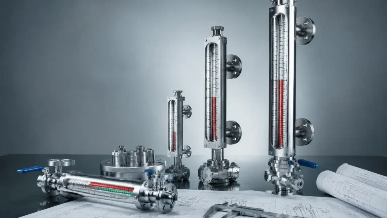
In many high-risk or critical applications, electronic level gauges are paired with mechanical indicators to provide redundancy. A common configuration involves mounting an electronic transmitter—such as a magnetostrictive or reed-switch sensor—externally to a magnetic level gauge chamber.
This setup allows the magnetic float inside the chamber to simultaneously flip the visual flags for local operators and trigger the electronic sensor for the control room. This dual-system approach ensures that level data is available even during a total power failure, as the local mechanical display remains functional. For more information on combining these technologies, you can Review product options and application support.
Key Selection Criteria for Industrial Applications
Choosing the wrong electronic level gauge can lead to frequent maintenance cycles or catastrophic overflow events. Engineers should confirm the following parameters before procurement:
1. Media Characteristics: Is the liquid corrosive, viscous, or prone to coating? Non-contact methods like ultrasonic or radar are preferred for corrosive media, while magnetostrictive sensors require a clean fluid to ensure the float does not stick.
2. Dielectric Constant: For radar-based electronic level gauges, the dielectric constant (εr) of the liquid is critical. Liquids with low dielectric constants (like oils or liquefied gases) reflect less energy, requiring high-sensitivity probes or coaxial designs.
3. Vessel Geometry: Internal obstructions such as agitators, heating coils, or baffles can interfere with radar or ultrasonic signals. In these cases, a bypass chamber or a stilling well may be necessary.
4. Operating Environment: Electronic components must be rated for the ambient temperature and potential explosive atmospheres (ATEX/IECEx ratings). In outdoor installations, surge protection against lightning and IP67/68 ingress protection are mandatory.
Installation and Calibration Considerations
Correct installation is as vital as the technology itself. Even the most advanced electronic level gauges will fail if installed incorrectly.
* Verticality: For float-based electronic gauges, the sensing rod or chamber must be installed perfectly vertical (typically within 3°). If tilted, friction between the float and the rod can cause "stiction," leading to erratic readings.
* Dead Zones: Every electronic level gauge has a "dead zone" or "blind zone" at the top and bottom of the sensor where measurement is impossible. For example, a magnetostrictive sensor may have a 50 mm dead zone at the top. This must be accounted for when calculating the usable volume of the tank.
* Grounding and Shielding: To prevent electromagnetic interference (EMI) from VFDs (Variable Frequency Drives) or heavy motors, electronic level gauges should be wired using shielded twisted-pair cables, with the shield grounded at the control cabinet end only.
* Calibration: While many modern electronic gauges are factory-calibrated, field verification is recommended. This can be done through a "dry" calibration (simulating the signal) or a "wet" calibration (comparing the reading against a physical dip-tape measurement).
Limitations and Common Risks
Despite their versatility, electronic level gauges have specific limitations that must be managed:
* Build-up and Scaling: In applications like wastewater or calcium-rich fluids, material can build up on probes or floats. This increases the weight of the float (causing it to sink deeper) or coats radar probes, leading to signal loss.
* Vapor and Pressure Changes: High-pressure steam or heavy vapor blankets can change the speed of sound (affecting ultrasonic) or the dielectric properties of the space above the liquid (affecting radar). Hydrostatic sensors are particularly sensitive to changes in head pressure if the tank is pressurized and not properly compensated.
* Turbulence: Rapid filling or agitation can cause surface turbulence. Electronic filters and damping settings in the transmitter can smooth out the signal, but extreme turbulence may require the use of a stilling well to protect the sensor and provide a calm surface for measurement.
Frequently Asked Questions (FAQs)
Q: Can electronic level gauges measure the interface between two liquids?
A: Yes, specifically magnetostrictive and Guided Wave Radar gauges. Magnetostrictive gauges use a float weighted to sink through the top layer (e.g., oil) and float on the bottom layer (e.g., water). GWR detects the change in dielectric constant at both the top surface and the interface.
Q: How often should an electronic level gauge be recalibrated?
A: For non-critical applications, an annual check is sufficient. In regulated industries or high-accuracy custody transfer, semi-annual or quarterly verification may be required. Instruments with no moving parts, like GWR, generally require less frequent calibration than float-based systems.
Q: What is the difference between a level transmitter and an electronic level gauge?
A: In industrial parlance, they are often used interchangeably. However, a "gauge" traditionally implies a device with a local display, while a "transmitter" focuses on sending the signal to a remote system. Most modern electronic level gauges perform both functions.
Q: Are electronic level gauges suitable for hygienic (food/pharma) applications?
A: Yes, provided they are designed with sanitary connections (e.g., Tri-Clamp), high-grade stainless steel (316L), and polished surfaces to prevent bacterial growth. Hydrostatic and GWR sensors are frequently used in these sectors.
Conclusion
Electronic level gauges represent a critical investment in industrial automation. By selecting the right technology—whether it be magnetostrictive, radar, or hydrostatic—and ensuring proper integration with Magnetic & Local Level Gauges, facilities can achieve higher precision, improved safety, and reduced manual oversight. When specifying these instruments, always prioritize the physical and chemical properties of the process media to ensure long-term reliability and accuracy.