Gauge Low to High
Gauge Low to High
In industrial process control, the ability to monitor a liquid level from its minimum to its maximum point is fundamental to operational safety and efficiency. Whether managing a small condensate tank or a massive chemical reactor, engineers require a reliable method to gauge low to high levels with precision. While electronic sensors offer remote monitoring capabilities, local visual indicators remain the primary line of defense and the most trusted point of verification for field operators.
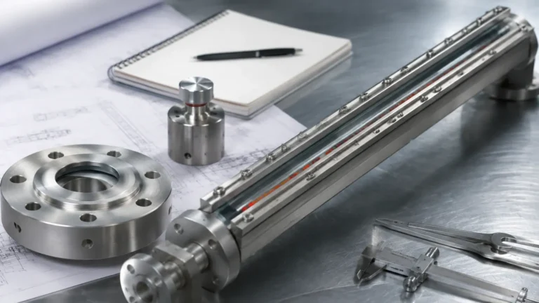
Magnetic & Local Level Gauges serve as the industry standard for this requirement. These instruments provide a continuous, high-visibility representation of the liquid level within a vessel, operating independently of power sources and offering a robust alternative to fragile glass gauges. This guide explores the engineering principles, selection criteria, and installation practices necessary to implement effective low-to-high level gauging in industrial environments.
Measurement Principles of Magnetic Level Gauges
To understand how a gauge tracks a level from low to high, one must first understand the principle of magnetic coupling and buoyancy. A magnetic level gauge consists of three primary components: the bypass chamber, the internal float, and the external indicator scale.
The Bypass Chamber
The bypass chamber is a vertical pipe, typically constructed from non-magnetic stainless steel (such as 304 or 316L), which is mounted to the side of the process vessel via nozzles. Because the chamber is connected to the vessel at both a low point and a high point, the liquid level inside the chamber equalizes with the level inside the tank, following the law of communicating vessels.
The Magnetic Float
Inside the chamber is a float specifically engineered to match the density of the process fluid. This float contains a high-intensity 360° magnetic ring. As the liquid level moves from the bottom of the chamber to the top, the float rises and falls accordingly. The buoyancy of the float is critical; if the fluid density changes significantly, the float may sit higher or lower in the liquid, affecting the accuracy of the "gauge low to high" reading.
The Visual Indicator
Mounted to the outside of the chamber is the indicator rail, which is hermetically sealed from the process. This rail contains a series of bi-color magnetic flaps or rollers (usually red and white). As the float moves past these flaps, the magnetic field causes them to rotate 180°. Typically, red indicates the presence of liquid (high level) and white indicates the presence of gas or vapor (low level). This provides a clear, high-contrast visual representation that can be read from a significant distance.
Defining the Measurement Range: From Low to High
When specifying a gauge, the term "gauge low to high" refers to the Center-to-Center (C-C) distance between the process connections. However, the actual measurable range is slightly different from the physical length of the pipe.
Center-to-Center (C-C) Distance
This is the distance between the center of the top process connection and the center of the bottom process connection. This dimension defines the primary installation footprint. Standard industrial gauges can range from 300 mm to over 6,000 mm. For ranges exceeding 6 meters, gauges are often manufactured in sections to facilitate transport and installation.
The "Blind Spot"
It is important to note that a magnetic level gauge has inherent "blind spots" at the extreme top and bottom of the chamber.
1. Bottom Blind Spot: The float requires a certain depth of liquid to begin floating. Additionally, there is a stop spring or buffer at the bottom of the chamber to prevent the float from hitting the end cap. Therefore, the "zero" or "low" mark on the scale is usually a few centimeters above the bottom process connection.
2. Top Blind Spot: Similarly, at the high end, the float cannot travel past the top of the chamber. The "high" mark on the scale is limited by the physical length of the chamber above the top process connection.
Engineers must account for these offsets when calibrating the gauge to ensure that the visual "low to high" transition matches the actual vessel volume requirements.
Selection Criteria for Gauge Low to High Applications
Choosing the right gauge requires a detailed analysis of the process conditions. The following table provides a general guideline for selecting gauge types based on common industrial parameters.
| Parameter | Standard Magnetic Gauge | High-Pressure Gauge | High-Temperature Gauge |
| :— | :— | :— | :— |
| Pressure Range | Up to 4.0 MPa (40 bar) | Up to 25.0 MPa (250 bar) | Up to 10.0 MPa (100 bar) |
| Temperature Range | -20°C to 150°C | -20°C to 250°C | -196°C to 450°C |
| Fluid Density | > 0.45 g/cm³ | > 0.60 g/cm³ | > 0.50 g/cm³ |
| Material | 304/316 Stainless Steel | Heavy-wall 316L/Ti | 316L with Insulation |
| Typical Application | Water tanks, oil storage | Steam boilers, HP separators | Hot oil, cryogenic liquids |
Key Evaluation Factors
1. Specific Gravity (Density): The float must be lighter than the liquid but heavy enough to withstand the operating pressure. If the liquid density is too low (e.g., liquefied gases), specialized titanium or thin-wall floats are required.
2. Viscosity: Highly viscous liquids can impede the movement of the float. If the liquid is prone to coating or clogging, the bypass chamber diameter may need to be increased, or internal coatings (like PTFE) may be applied.
3. Corrosive Properties: For aggressive chemicals like acids or brine, the chamber and float must be constructed from compatible materials such as Hastelloy, Monel, or plastic-lined (PP/PVDF/PTFE) stainless steel.
4. Operating Pressure: As pressure increases, the float must be reinforced to prevent collapse. However, a heavier float requires a higher liquid density to remain buoyant.
Installation Considerations for Accurate Tracking
To ensure the gauge accurately reflects the low to high level transitions, proper installation is paramount. Failure to follow these guidelines can result in float sticking or inaccurate readings.
Vertical Alignment
The bypass chamber must be installed perfectly vertical. Even a slight tilt (greater than 3 degrees) can cause the internal float to rub against the chamber walls, leading to friction that prevents the float from moving smoothly as the level changes. This is the most common cause of "stuck" level readings.
Magnetic Interference
Because the system relies on magnetic coupling, the gauge must be kept away from large ferrous structures or strong electromagnetic fields (such as high-power motors or transformers). If the gauge is installed too close to a steel support beam, the magnetic field of the float may be distorted, causing the external flaps to fail to flip.
Venting and Draining
Every magnetic level gauge should be equipped with a vent valve at the top and a drain valve at the bottom.
* Venting: Allows air or gas trapped in the chamber to escape, ensuring the liquid can rise to the "high" point.
* Draining: Allows the chamber to be cleared of sediment or sludge that might accumulate at the "low" point and interfere with float movement.
Initial Startup
When commissioning a gauge, the process valves should be opened slowly. A sudden surge of high-pressure liquid can slam the float into the top of the chamber, potentially damaging the magnetic ring or the internal stop springs.

Limitations and Risks
While Magnetic & Local Level Gauges are highly reliable, they are not universal solutions. Engineers should be aware of the following limitations:
1. Particulate Matter: If the process fluid contains magnetic particles (e.g., iron filings or pipe scale), these particles will adhere to the magnetic float. Over time, this buildup increases the float's weight and diameter, eventually causing it to sink or jam.
2. Boiling and Flashing: In applications where the liquid is near its boiling point, rapid flashing inside the chamber can create turbulence that causes the float to bounce erratically, leading to "chattering" of the indicator flaps.
3. Interface Measurement: Gauging the interface between two liquids (e.g., oil and water) requires a float precisely weighted to sink in the upper liquid but float on the lower liquid. This requires very stable density profiles.
4. Coating Liquids: Extremely sticky or crystallizing fluids can coat the inside of the chamber, eventually narrowing the diameter until the float can no longer move from low to high.
Enhancing the Local Gauge
Modern industrial requirements often demand that the local "low to high" visual data be transmitted to a Control Room (DCS/PLC). This is achieved by adding accessories to the magnetic level gauge without breaking the pressure boundary:
* Reed Switch Transmitters: A chain of reed switches and resistors mounted alongside the chamber. The float's magnet triggers these switches, providing a 4-20mA signal proportional to the level.
* Magnetostrictive Transmitters: These offer much higher precision (up to 0.1mm) and are ideal for custody transfer or high-accuracy inventory management.
* Level Switches: Magnetic bistable switches can be clamped to the chamber at specific "Low" or "High" setpoints to trigger alarms or pump start/stop sequences.
Frequently Asked Questions (FAQ)
Q: Can I use a magnetic level gauge for underground tanks?
A: No, magnetic level gauges require side-mounting or a bypass configuration. For underground tanks, top-mounted solutions like ultrasonic sensors or hydrostatic transmitters are typically preferred.
Q: How do I reset the indicator flaps if they get out of sync?
A: You can reset the flaps by manually sliding a small external magnet along the indicator rail to flip them back to the correct color (usually white for the empty portion).
Q: What is the maximum temperature a magnetic gauge can handle?
A: With specialized high-temperature floats and insulation jackets, some gauges can operate at temperatures up to 450°C. However, the indicator rail must be offset or cooled to prevent damage to the magnets.
Q: Does the gauge work with pressurized gases above the liquid?
A: Yes, as long as the chamber is vented to the top of the vessel, the pressure will equalize, and the float will respond only to the liquid level.
Summary
Tracking a liquid level from low to high is a critical requirement for process safety. Magnetic & Local Level Gauges provide a clear, durable, and maintenance-friendly solution for this task. By understanding the buoyancy requirements of the float and the physical dimensions of the bypass chamber, engineering teams can ensure accurate visual indication across the entire operating range of their vessels. Proper selection of materials and attention to installation details like verticality and magnetic clearance will ensure years of reliable service in even the most demanding industrial environments.