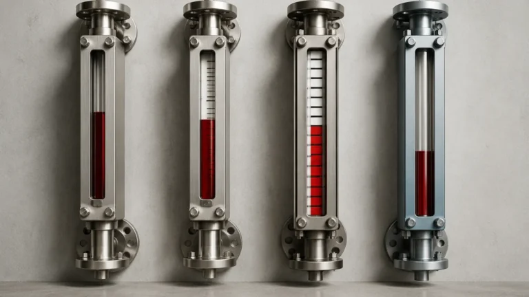
Lh Gauge
Lh Gauge
In the landscape of industrial process control, the ability to monitor liquid levels accurately and safely is paramount. Among the various technologies available, the lh gauge—often configured as a high-level (LH) visual indicator within the broader category of magnetic level gauges—serves as a critical tool for operators. These instruments provide a clear, real-time visual representation of tank levels without the risks associated with traditional glass sight gauges. This guide explores the engineering principles, selection criteria, and installation best practices for incorporating these gauges into modern industrial workflows.
Understanding the Principles of Local Level Indication
Local level indication refers to the measurement and display of fluid levels directly at the vessel or tank, rather than solely transmitting data to a remote control room. The most reliable form of local indication in high-pressure or hazardous environments is the magnetic level gauge.
The Buoyancy and Magnetic Coupling Principle
The operation of an lh gauge relies on two fundamental physical principles: buoyancy and magnetism. Unlike a standard sight glass where the process fluid is contained within a fragile glass tube, a magnetic gauge utilizes a bypass chamber (typically constructed from stainless steel or high-performance alloys) connected to the side of the tank.
Inside this chamber, a float is engineered to match the specific gravity of the liquid being measured. This float contains an internal permanent magnet assembly. As the liquid level in the tank rises or falls, the float moves accordingly within the chamber. Outside the chamber, a visual indicator—consisting of a series of bi-color magnetic flags or a magnetic follower—is mounted. The magnetic field from the float penetrates the non-magnetic chamber wall, causing the flags to rotate or the follower to move. This provides a clear, high-visibility representation of the liquid level.
Why "LH" Matters in Level Gauging
The designation of an lh gauge typically refers to its role in monitoring high-level (Level-High) conditions. In many industrial applications, reaching a "High" or "High-High" level can lead to overfills, equipment damage, or environmental hazards. An lh gauge is often equipped with additional magnetic switches or transmitters to provide both local visual confirmation and automated electrical signals for alarm or shutdown systems. This dual-purpose functionality makes Magnetic & Local Level Gauges indispensable for safety-critical applications.
Key Components of Magnetic & Local Level Gauges
To ensure reliability in demanding environments, several components must work in harmony:
1. The Chamber: The vertical pipe connected to the vessel. It must be made of non-magnetic material (usually 316/316L Stainless Steel, Titanium, or Hastelloy) to allow the magnetic field to pass through to the indicator.
2. The Float: A precision-engineered sealed vessel designed to withstand the process pressure while remaining buoyant. The magnet array inside is usually a 360-degree ring magnet to ensure coupling regardless of float rotation.
3. The Indicator Rail: A sealed glass or polycarbonate tube containing the magnetic flags (usually red/white or yellow/black). These flags are often fluorescent for better visibility in low-light conditions.
4. Process Connections: Flanged or NPT connections that link the chamber to the tank. These are typically located at the side-side, side-bottom, or top-bottom of the vessel.
Technical Selection Criteria for an Lh Gauge
Selecting the correct lh gauge requires a detailed understanding of the process conditions. Engineers must confirm several variables before procurement to avoid measurement errors or mechanical failure.
Material Compatibility and Pressure Ratings
The chamber and float material must be chemically compatible with the process fluid. For corrosive chemicals, PTFE-lined chambers or exotic alloys are required. Furthermore, the float must be designed to withstand the maximum operating pressure. If the pressure is too high for a standard float, it may collapse, causing the gauge to fail.
Specific Gravity (SG)
Because the gauge operates on buoyancy, the float must be weighted precisely for the fluid's specific gravity. A float designed for water (SG 1.0) will not work correctly in a light hydrocarbon (SG 0.6). If the SG changes due to temperature fluctuations, the accuracy of the lh gauge may be affected.
Visibility and Scale
For local level gauges, visibility is the primary objective. Operators should determine the required viewing distance. Magnetic flags are generally easier to read from a distance than a magnetic follower. Scales can be provided in metric units (mm/cm), imperial units (inches/feet), or percentage of volume.
Comparison of Local Level Technologies
| Feature | Magnetic LH Gauge | Reflex Glass Gauge | Transparent Glass Gauge |
| :— | :— | :— | :— |
| Measurement Principle | Magnetic Coupling | Light Refraction | Direct Visual |
| Max Pressure | Up to 200 bar (2900 psi) | Up to 35 bar (500 psi) | Up to 100 bar (1450 psi) |
| Max Temperature | Up to 450°C (842°F) | Up to 400°C (752°F) | Up to 400°C (752°F) |
| Maintenance | Low (No glass to clean) | High (Glass staining) | High (Requires mica shields) |
| Safety | High (Process contained) | Moderate (Risk of breakage) | Moderate (Risk of breakage) |
Installation Guidelines and Best Practices
Proper installation is critical for the long-term accuracy and safety of an lh gauge. Failure to follow engineering standards can lead to "stuck" floats or inaccurate readings.
Vertical Alignment
The bypass chamber must be installed perfectly vertical. Any significant tilt can cause the float to rub against the chamber walls, leading to friction that prevents the float from following the liquid level accurately. Use a spirit level or plumb line during installation.
Isolation and Venting
Every lh gauge should be installed with isolation valves (ball or gate valves) between the tank and the gauge chamber. This allows for maintenance or float replacement without draining the entire vessel. Additionally, a vent valve at the top and a drain valve at the bottom of the chamber are essential for commissioning and cleaning.
Magnetic Interference
Since the gauge relies on magnetic fields, it must be kept away from large ferrous structures or high-voltage cables that could create electromagnetic interference. Ensure that any heat tracing or insulation jackets used on the gauge do not contain metallic components that could shield the magnetic field.
Commissioning Steps
1. Check the Float Orientation: Ensure the float is inserted into the chamber with the "Top" marking facing up.
2. Slow Fill: When opening the isolation valves, do so slowly. A sudden surge of liquid can slam the float into the top of the chamber, potentially damaging the magnet assembly.
3. Zeroing: Once the liquid enters the chamber, verify that the indicator flags flip to the correct color (usually red for liquid, white for gas/vapor).

Limitations and Operational Considerations
While highly reliable, the lh gauge does have specific limitations:
* Viscosity: Extremely viscous liquids or those that tend to crystallize can impede float movement. In such cases, internal coatings or steam heating jackets may be necessary.
* Particulates: Ferrous particles in the process fluid can accumulate on the float's magnet, eventually weighing it down or causing it to stick to the chamber wall. Magnetic filters (traps) in the process lines can mitigate this.
* Coating/Scaling: If the process fluid leaves a heavy deposit on the chamber walls, the clearance between the float and the wall may decrease, leading to mechanical binding.
Maintenance and Safety Protocols
One of the primary advantages of magnetic Magnetic & Local Level Gauges is their low maintenance requirement compared to sight glasses. However, a routine inspection schedule should be implemented:
* Visual Inspection: Check for leaks at the flanges and ensure the indicator rail is clean and readable.
* Float Movement Check: Periodically drain the chamber using the bottom drain valve to ensure the float moves freely and the indicator returns to the zero position.
* Switch Testing: If the lh gauge is equipped with high-level switches, these should be tested during scheduled shutdowns to ensure they trigger the appropriate alarms.
Frequently Asked Questions (FAQ)
Q: Can an lh gauge be used for interface measurement between two liquids?
A: Yes. By engineering a float with a specific gravity that falls between the SGs of the two liquids (e.g., oil and water), the float will sink through the upper layer and float on the lower layer, effectively indicating the interface level.
Q: What is the maximum length for a magnetic level gauge?
A: While individual chambers are typically limited to 6 meters (approx. 20 feet) due to shipping and structural constraints, sections can be joined with flanges to reach greater heights.
Q: Are these gauges suitable for cryogenic applications?
A: Yes, but they require specialized insulation and "frost-free" extensions for the indicator rail to prevent ice buildup from obscuring the visual display.
Q: How does an lh gauge handle high-vibration environments?
A: For applications with significant vibration (such as near pumps or compressors), indicators can be equipped with dampened flags or magnetic followers that resist accidental flipping due to mechanical shock.
By following these engineering guidelines and selecting the appropriate configuration for the specific process environment, the lh gauge provides a robust, low-maintenance solution for local level monitoring, ensuring both operational efficiency and personnel safety.