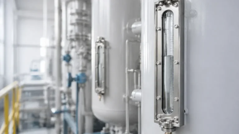
Local Level Gauges
Local Level Gauges
In industrial process control, the ability to verify liquid levels visually at the tank side remains a critical safety and operational requirement. While modern facilities rely heavily on remote sensors and automated control systems, local level gauges serve as the primary physical reference point for operators. These instruments provide a direct, mechanical representation of the liquid level within a vessel, functioning independently of power supplies or complex electronic signal processing.
For engineers and plant managers, choosing the correct local indicator involves understanding the mechanical forces at play and the environmental constraints of the application. This guide explores the principles, selection criteria, and installation requirements for the most reliable visual measurement technologies used in water treatment, chemical processing, and oil and gas industries.
Understanding the Principles of Local Level Gauges
Local level measurement is primarily achieved through two physical principles: direct visual observation of the liquid (glass gauges) or magnetic coupling (magnetic level gauges).
The Principle of Magnetic Coupling
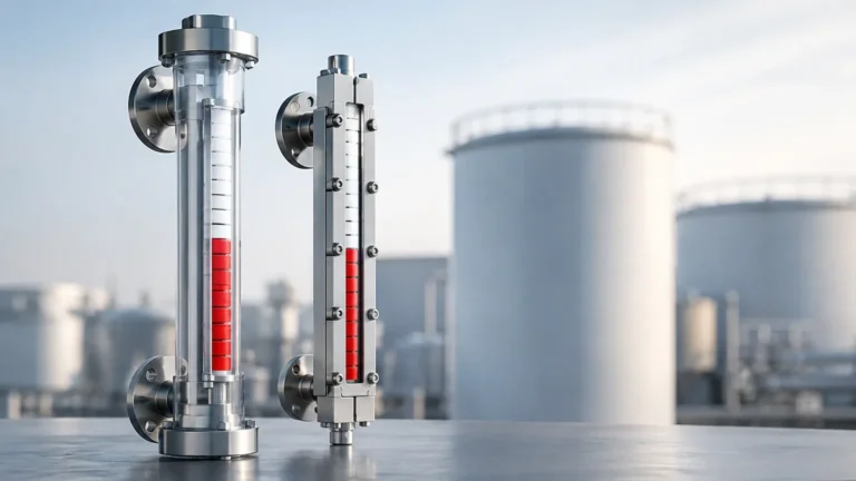
Magnetic & Local Level Gauges are the most common solution for high-pressure or hazardous applications. These devices operate on the principle of buoyancy and magnetic attraction. The system consists of three main components:
1. The Bypass Chamber: A vertical pipe (column) connected to the side of the tank via process flanges. The liquid level in the chamber matches the level in the tank according to the law of communicating vessels.
2. The Magnetic Float: Inside the chamber, a float is engineered to the specific gravity of the process liquid. This float contains a high-intensity 360° magnetic ring.
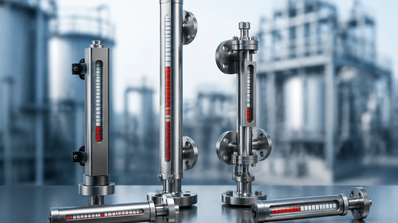
3. The Indicator Rail: Mounted to the outside of the chamber, this rail contains a series of bicolored (usually red and white) magnetic flaps or rollers.
As the liquid level rises or falls, the float moves accordingly. The magnetic field from the float penetrates the chamber wall and flips the external flaps. Because the indicator is physically isolated from the process fluid, there is no risk of leaks through the glass, making it a safer alternative to traditional sight glasses.
The Principle of Communicating Vessels (Glass Gauges)
Traditional local level gauges like reflex or transparent glass gauges use the simplest form of measurement. By connecting a glass tube or windowed metal body to the tank, the liquid enters the gauge and reaches the same height as the liquid in the vessel.
* Reflex Gauges: Use prisms cut into the glass to refract light. The liquid-filled area appears dark, while the gas/vapor space appears silvery-white, providing a high-contrast line.
* Transparent Gauges: Feature glass on both sides of the chamber, allowing light to pass through. This is essential for observing liquid interface or color.
Types of Local Level Gauges in Industrial Applications
Selecting the right gauge type depends on the visibility requirements, the toxicity of the medium, and the operating pressure.
1. Magnetic Level Gauges (MLG)
MLGs are the industry standard for hazardous media. Since the indicator is not in contact with the fluid, they are ideal for acids, hydrocarbons, and high-pressure steam. They can be fitted with transmitters (4-20mA) or switches to provide both local and remote monitoring simultaneously.
2. Reflex Glass Gauges
These are used for clean, non-viscous liquids where a simple visual check is sufficient. They are cost-effective but limited by the pressure-temperature rating of the glass and the potential for the glass to become clouded or etched by the process media over time.
3. Transparent Glass Gauges
Best suited for interface measurement (e.g., oil and water) or when the color of the liquid must be monitored. In high-pressure steam applications, transparent gauges are often fitted with mica shields to protect the glass from erosion.
4. Tubular Glass Gauges
Common in low-pressure water treatment or atmospheric tanks. These consist of a simple clear tube protected by a metal guard. While inexpensive, they are the most fragile and are generally avoided in chemical or high-temperature service.
Selection Criteria for Local Level Gauges
When specifying a gauge, engineers must balance material compatibility with mechanical safety. The following table provides a general framework for selecting between magnetic and glass-based local level gauges.
| Feature | Magnetic Level Gauges | Glass Level Gauges (Reflex/Transparent) |
| :— | :— | :— |
| Max Pressure | Up to 250 bar (3625 psi) | Up to 150 bar (2175 psi) |
| Max Temperature | Up to 450°C (842°F) | Up to 400°C (752°F) with mica |
| Safety Profile | High (No glass, no leaks) | Moderate (Glass breakage risk) |
| Visibility | Excellent (Visible from 30m+) | Moderate (Requires close proximity) |
| Media Compatibility | Highly Corrosive / Toxic | Clean / Non-etching liquids |
| Maintenance | Low (Self-cleaning floats) | High (Cleaning/Gasket replacement) |
| Interface Detection | Yes (Specific float required) | Yes (Transparent type only) |
Material Selection
The body of the gauge must be compatible with the process fluid. Common materials include:
* 316L Stainless Steel: The standard for most industrial water and chemical applications.
* Special Alloys (Hastelloy, Monel): Used for highly aggressive acids or seawater.
* Plastics (PP, PVDF, PVC): Used for low-pressure corrosive applications where metals are unsuitable.
* PTFE Lining: Provides the strength of a steel chamber with the corrosion resistance of fluoropolymers.
Installation and Commissioning Best Practices
Correct installation is paramount to the accuracy and longevity of local level gauges. Failure to follow these guidelines often results in float damage or inaccurate readings.
1. Vertical Alignment: The gauge must be installed perfectly vertical. Even a slight tilt can cause the float to rub against the chamber wall, leading to friction and "sticking."
2. Isolation Valves: Always install high-quality isolation valves between the tank and the gauge. This allows for maintenance or gauge replacement without draining the entire vessel.
3. Venting and Draining: Ensure the gauge has a vent plug at the top and a drain valve at the bottom. During commissioning, the gauge should be filled slowly to avoid a "pressure shock" that could crush the float.
4. Magnetic Interference: For magnetic level gauges, ensure that no large ferrous structures or high-voltage cables are within 100mm (4 inches) of the indicator rail, as these can interfere with the magnetic coupling.
5. Center-to-Center Distance: Accurate measurement of the nozzle distance on the tank is required. Standard gauges are built to specific center-to-center (C-C) dimensions, often ranging from 300mm to 6000mm (approx. 1ft to 20ft).
Limitations and Operational Constraints
While highly reliable, local level gauges have specific limitations that must be addressed during the design phase:
* Viscosity: Extremely viscous liquids (above 500 cP) can impede the movement of the float in a magnetic gauge or coat the glass in a sight gauge, making it unreadable. Heating jackets are often required for such applications.
* Magnetic Particles: If the process fluid contains iron filings or magnetic scales, these will cling to the magnetic float, eventually causing it to jam. Magnetic traps should be installed in the bypass line in these cases.
* Specific Gravity Fluctuations: Magnetic floats are weighted for a specific density. If the liquid density changes significantly (e.g., due to temperature swings or mixing), the float will sit higher or lower in the liquid, introducing a measurement error.
* Coating and Scaling: In water treatment, calcium buildup can obscure glass gauges. Regular flushing via the drain valve is necessary to maintain visibility.
Maintenance and Troubleshooting
A proactive maintenance schedule ensures that local indicators remain a dependable backup to electronic systems.
* Periodic Flushing: Open the drain valve periodically to remove sediment from the bottom of the chamber. This prevents the float from getting stuck in the "zero" position.
* Float Inspection: For magnetic gauges, the float should be inspected annually for signs of corrosion or collapsed walls, especially in high-pressure service.
* Gasket Integrity: In glass gauges, gaskets are the most common point of failure. They should be replaced whenever the glass is removed for cleaning.
* Indicator Calibration: If the flaps on a magnetic gauge appear "scrambled," a small external magnet can be used to reset them to the correct orientation.
Frequently Asked Questions (FAQ)
Q: Can a magnetic level gauge be used for underground tanks?
A: Yes, but it requires a "top-mount" configuration. In this setup, a float on a rod moves within a chamber above the tank, and the magnet is located at the top of the rod to actuate the indicator.
Q: How do I choose between a 4-20mA transmitter and a local level gauge?
A: You shouldn't have to choose. Many local level gauges allow for a reed-chain or magnetostrictive transmitter to be strapped to the outside of the chamber, providing both a local visual display and a remote signal for the PLC/SCADA system.
Q: What happens if the float is installed upside down?
A: The gauge will not function correctly. Most floats are clearly marked with a "TOP" arrow. If installed incorrectly, the magnetic center will not align with the indicator, and the buoyancy will be off-set.
Q: Are local level gauges suitable for hygienic (food/pharma) applications?
A: Yes, but they must be specifically designed with sanitary flanges (Tri-clamp) and polished internal surfaces (Ra < 0.8μm) to prevent bacterial growth.
Conclusion
Local level gauges remain an indispensable component of industrial instrumentation. By providing a clear, mechanical verification of tank contents, they bridge the gap between automated data and physical reality. Whether utilizing the high-visibility and safety of a magnetic level gauge or the direct observation of a reflex glass, proper selection based on pressure, temperature, and media characteristics is the key to long-term operational safety. For complex applications involving high temperatures or corrosive chemicals, consulting with a manufacturer for a customized float and chamber design is recommended to ensure accuracy and durability.