Location Gauges
Location Gauges
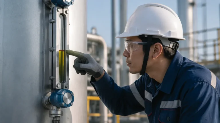
In industrial process control, the ability to verify fluid levels directly at the tank or vessel is a fundamental requirement for safety, redundancy, and operational efficiency. While modern facilities rely heavily on remote sensing technologies like radar or ultrasonic transmitters, the use of location gauges—specifically local visual indicators—remains an industry standard. These instruments provide a physical, real-time representation of the liquid level without requiring external power, serving as the primary point of reference for field operators.
Local level indication is often categorized under the broader heading of Magnetic & Local Level Gauges. These devices are designed to withstand harsh industrial environments, offering a clear visual interface where electronic systems might fail or where manual verification is mandated by safety protocols. This guide explores the principles, selection criteria, and installation requirements for these essential instruments.
Principles of Operation for Local Level Measurement
To select the correct instrument, it is necessary to understand the physics behind the two primary types of location gauges used in modern engineering: magnetic bypass gauges and direct-reading glass gauges.
Magnetic Level Gauges (MLG)
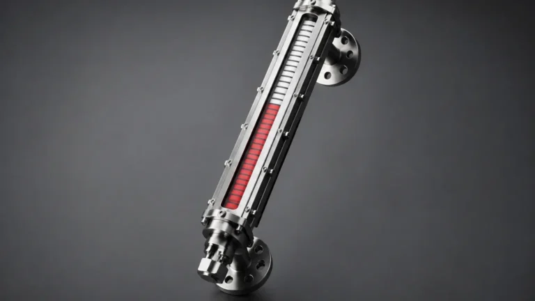
The magnetic level gauge operates on the principle of buoyancy and magnetic coupling. The system consists of a bypass chamber (a vertical pipe) mounted to the side of the process vessel. Inside this chamber is a float containing a high-intensity omnidirectional magnet. As the liquid level in the vessel rises and falls, the float moves accordingly within the chamber.
Outside the chamber, a visual indicator rail is attached. This rail contains a series of magnetized flaps (often colored red and white) or a follower. As the float passes these flaps, the magnetic field causes them to rotate 180 degrees, changing their color. Because the fluid is entirely contained within the pressure-tight chamber, there is no risk of glass breakage or leaks reaching the operator. This "magnetic coupling" ensures that the visual indication is physically linked to the float position without any direct contact between the process media and the indicator.
Direct-Reading Glass Gauges
Direct-reading gauges, such as reflex or transparent sight glasses, work on the principle of communicating vessels. The liquid level in the glass tube or window matches the level in the tank.
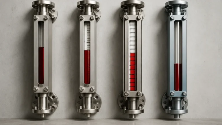
* Reflex Gauges: These use a special prism-shaped glass. When light hits the glass in the area occupied by gas/vapor, it is reflected back, appearing bright white. In the area occupied by liquid, the light is absorbed, making the liquid appear dark. This provides a high-contrast line that is easy to read from a distance.
* Transparent Gauges: These feature two pieces of flat glass on either side of the liquid column. They are used primarily when the interface between two liquids must be observed or when the color/clarity of the fluid is a critical process parameter.
Comparing Technologies: Magnetic vs. Glass Gauges
When evaluating location gauges for a specific project, engineers must weigh the benefits of magnetic systems against traditional glass indicators. The following table summarizes the key differences:
| Feature | Magnetic Level Gauges | Glass Level Gauges (Reflex/Transparent) |
| :— | :— | :— |
| Safety | High; no glass to break, fluid is fully contained. | Moderate; risk of glass failure under thermal shock. |
| Visibility | Excellent; high-contrast flags visible from 30+ meters. | Moderate; requires proximity to distinguish level. |
| Pressure Rating | Up to 400 bar (40 MPa) depending on materials. | Generally lower; limited by glass strength. |
| Temperature | -200°C to +450°C. | Limited by gasket and glass tolerances. |
| Maintenance | Low; minimal cleaning required for the indicator. | High; glass can become stained or etched. |
| Redundancy | Can be fitted with transmitters and switches. | Purely visual; difficult to automate. |
| Cost | Higher initial investment. | Lower initial investment. |
| Media | Not suitable for highly viscous or magnetic fluids. | Suitable for most fluids, provided glass is compatible. |
Key Selection Criteria for Industrial Location Gauges
Selecting the appropriate location gauges requires a detailed analysis of the process conditions. Failure to account for fluid properties or environmental factors can lead to inaccurate readings or mechanical failure.
1. Fluid Density and Specific Gravity
For magnetic gauges, the float must be specifically engineered to match the fluid's density. If the fluid is too light (low specific gravity), a standard float may sink; if it is too heavy, the float may sit too high, leading to an offset in the reading. In applications involving liquefied gases or hydrocarbons, specific gravity can change with temperature, requiring a float design that accounts for these fluctuations.
2. Material Compatibility
The wetted parts of the gauge—the chamber, float, and gaskets—must be compatible with the process media. Common materials include:
* Stainless Steel (304/316L): The standard for water treatment and general chemical applications.
* Special Alloys (Hastelloy, Monel, Titanium): Used for highly corrosive acids or seawater applications.
* Plastics (PVC, PP, PVDF): Ideal for low-pressure, highly corrosive chemical storage where metals are unsuitable.
3. Pressure and Temperature Ratings
Location gauges are pressure vessels. Designers must ensure the gauge's flange rating and wall thickness meet the Maximum Allowable Working Pressure (MAWP) of the system. High-temperature applications may require insulation blankets or specialized steam jackets to prevent the process fluid from crystallizing or becoming too viscous to allow float movement.
4. Visibility and Orientation
The orientation of the indicator rail should be specified during the design phase. In large-scale industrial plants, location gauges should be positioned so that they are visible from the primary walkways or operator access platforms. For very tall tanks, multiple gauge sections may be staggered to provide continuous coverage over several meters.
Installation and Maintenance Best Practices
Proper installation is critical to the longevity and accuracy of location gauges. Even the most robust magnetic gauge can fail if mechanical stresses are introduced during mounting.
Installation Checklist
1. Vertical Alignment: The bypass chamber must be installed perfectly vertical. Even a slight tilt can cause the internal float to rub against the chamber walls, leading to friction and "sticking."
2. Isolation Valves: Always install high-quality isolation valves (ball or globe valves) between the vessel and the gauge. This allows for maintenance or cleaning without draining the entire process tank.
3. Venting and Draining: Ensure the gauge is equipped with a vent plug at the top and a drain valve at the bottom. This is essential for removing trapped air during commissioning and for flushing out sediment during routine maintenance.
4. Magnetic Interference: Keep the gauge away from large external magnetic fields, such as those generated by high-voltage motors or certain types of heaters, as these can interfere with the coupling between the float and the indicator flags.
Maintenance Guidance
While magnetic location gauges are largely low-maintenance, they are not "set and forget" devices. In water treatment or oil and gas applications, sediment or paraffin can build up inside the chamber. Regular flushing via the drain valve is recommended. If the indicator flags appear to be sticking, the indicator rail should be inspected for debris or physical damage to the pivot points.

Limitations and Operational Risks
While highly reliable, location gauges have specific limitations that engineers must acknowledge:
* Coating and Fouling: If the process fluid is prone to scaling or heavy coating, the float may eventually become weighed down or stuck. In such cases, a non-contact technology like radar might be a better primary instrument, with the magnetic gauge serving as a secondary backup.
* Extreme Vibration: In applications near heavy machinery, excessive vibration can cause the indicator flags to flip prematurely. Specialized dampened indicators are available for these environments.
* Magnetic Particles: If the process fluid contains ferrous particles (e.g., iron filings in a recirculating oil system), these particles will migrate to the float's magnet, eventually causing it to jam. Magnetic traps or filters must be installed upstream in these scenarios.
Frequently Asked Questions (FAQs)
Q: Can location gauges be used for interface measurement?
A: Yes. Magnetic level gauges are excellent for interface measurement (e.g., oil over water). The float is weighted to sink through the upper, lighter liquid and float on the lower, heavier liquid.
Q: Do these gauges require power?
A: Standard visual location gauges are purely mechanical and require no power. However, they can be augmented with reed switches or 4-20mA transmitters if remote signaling is also required.
Q: What is the maximum height for a single gauge?
A: While individual chambers can be manufactured up to 6 meters, shipping and structural support become difficult. For taller requirements, gauges are typically built in sections and joined with flanges.
Q: How do I handle fluids that might freeze?
A: For cold-weather environments or fluids with high pour points, location gauges can be equipped with electric heat tracing or steam jackets to maintain a consistent temperature within the bypass chamber.
Conclusion
Location gauges remain a cornerstone of industrial level monitoring, providing the essential visual confirmation needed for safe and efficient operations. By understanding the principles of magnetic coupling and buoyancy, and by carefully selecting materials that match the process environment, facilities can ensure long-term reliability. Whether used in water treatment, chemical processing, or oil and gas, these instruments bridge the gap between automated control systems and manual field oversight.
For technical specifications and to explore customizable options for your facility, Review product options and application support to find the right solution for your specific pressure and temperature requirements.