Pressure Gauge Locations
Pressure Gauge Locations
In industrial process engineering, the accuracy of a pressure reading is as much a function of the instrument’s quality as it is a function of its placement. Selecting the correct pressure gauge locations is a critical task for ensuring system safety, operational efficiency, and equipment longevity. Whether monitoring a high-pressure steam line or a chemical storage tank, the physical point of measurement determines whether the data reflects the true state of the process or is skewed by turbulence, friction losses, or hydrostatic head.
This guide explores the technical principles of pressure measurement, provides strategic recommendations for instrument placement across various industrial components, and examines how these measurements integrate with other local indicators, such as Magnetic & Local Level Gauges.
Fundamental Principles of Pressure Measurement
Before determining the optimal pressure gauge locations, it is essential to understand the underlying physics of how these instruments interact with the process media. Most industrial pressure gauges utilize a Bourdon tube, diaphragm, or bellows as the sensing element. These elements deform under pressure, and this mechanical movement is translated into a needle position on a dial.
Static vs. Dynamic Pressure
In a flowing system, total pressure is the sum of static pressure and dynamic pressure.
1. Static Pressure: The pressure exerted by a fluid at rest or measured perpendicular to the flow direction.
2. Dynamic Pressure: The kinetic energy of the fluid per unit volume.
For process control, engineers are typically interested in static pressure. Therefore, the pressure tap must be installed flush with the internal wall of the pipe and perpendicular to the flow. If the sensing element protrudes into the flow stream or is angled against the flow, the reading will include a portion of the dynamic pressure, leading to an artificially high reading.
Laminar vs. Turbulent Flow
Pressure gauge locations must be chosen to avoid areas of high turbulence. Turbulence causes rapid fluctuations in the sensing element, leading to "pointer flutter," which accelerates wear on the internal movement (gears and hairsprings). To ensure laminar flow at the point of measurement, gauges should be placed away from elbows, valves, T-junctions, and pump discharges.
Strategic Placement of Pressure Gauges in Process Systems
The location of a gauge is determined by the specific goal of the measurement: protecting equipment, monitoring performance, or ensuring safety. Below are the standard industry practices for common equipment.
Pump Systems
Monitoring pump performance requires gauges on both the suction and discharge sides.
* Suction Side: The gauge should be located at least 2 to 5 pipe diameters upstream of the pump inlet. This helps monitor the Net Positive Suction Head (NPSH) and detect potential cavitation or intake clogging.
* Discharge Side: The gauge should be placed on a straight run of pipe before any check valves or throttling valves. This allows operators to verify the pump is meeting its curve requirements.
Filtration and Strainer Units
Differential pressure is the primary indicator of filter health. Gauges should be located immediately before and after the filter housing. A significant increase in the pressure drop (delta-P) indicates that the filter element is saturated and requires cleaning or replacement. In many critical applications, a single differential pressure gauge is used, but local independent gauges provide redundancy.
Heat Exchangers
Pressure gauge locations in heat exchangers are vital for detecting internal scaling or tube leaks. Gauges should be installed at the inlet and outlet of both the process side and the cooling/heating side. An unexpected pressure drop across the exchanger often indicates fouling, while a pressure equalization between the two sides may signal a ruptured tube.
Pressure Vessels and Storage Tanks
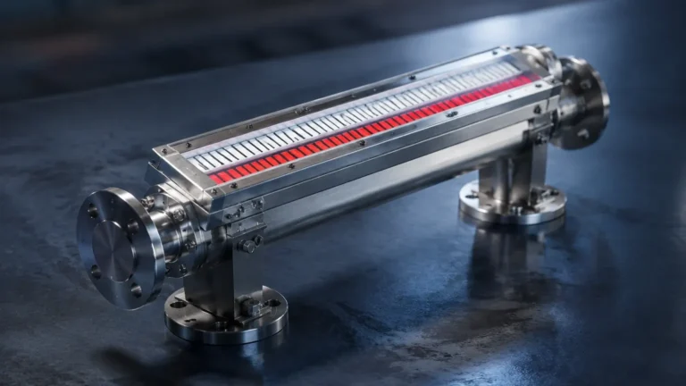
In pressurized vessels, the gauge is typically located at the top of the vessel in the vapor space to monitor the internal operating pressure. However, when dealing with liquid storage, pressure measurement is often used in conjunction with level measurement. While hydrostatic transmitters provide electronic data, Magnetic & Local Level Gauges offer a mechanical, high-visibility reference that remains functional during power outages. Placing a pressure gauge near the top and a level gauge on the side of the vessel provides a comprehensive view of the tank's status.
Technical Selection Criteria for Specific Locations
Not all pressure gauges are suitable for every location. The environment at the measurement point dictates the required specifications. The following table outlines selection criteria based on the physical location and process conditions.
| Location Characteristic | Recommended Gauge Feature | Reason |
| :— | :— | :— |
| High Vibration (near pumps/compressors) | Liquid-filled case (Glycerin/Silicone) | Dampens internal movement and prevents pointer flutter. |
| Corrosive Media (chemical lines) | Diaphragm Seal (Chemical Seal) | Isolates the internal gauge mechanism from the aggressive process fluid. |
| High Temperature (steam lines) | Pigtail or Coil Siphon | Dissipates heat to protect the sensing element from thermal damage. |
| Pulsating Pressure (reciprocating pumps) | Snubber or Orifice Restrictor | Slows the response time to prevent rapid mechanical wear. |
| Outdoor/Washdown Areas | IP65/IP67 Rated Housing | Prevents moisture ingress and internal corrosion. |
Installation Guidelines and Best Practices
Even the best-selected pressure gauge locations can yield poor results if the installation is flawed. Adhering to the following engineering standards ensures long-term reliability.
Orientation and Accessibility
Whenever possible, gauges should be installed in a vertical position. This prevents the accumulation of debris or air pockets in the sensing element. Furthermore, the gauge face must be oriented toward the primary operator walkway. If a gauge is located more than 2 meters (approx. 6.5 feet) above the floor, a larger dial size (e.g., 150mm / 6 inches) should be used to ensure readability from the ground.
The Use of Isolation Valves
Every pressure gauge should be installed with an isolation valve (typically a needle valve or a ball valve). This allows for the removal and calibration of the instrument without shutting down the entire process line. For high-pressure applications, a "block and bleed" manifold is recommended, allowing the operator to safely vent the pressure trapped between the valve and the gauge before removal.
Piping and Impulse Lines
If the gauge cannot be mounted directly to the process pipe, impulse lines are used. These lines should be as short as possible to minimize lag time. For liquid service, the line should slope upward toward the gauge to allow air bubbles to escape. For gas service, the line should slope downward to prevent condensate from pooling in the gauge.

Limitations and Common Risks of Incorrect Placement
Choosing improper pressure gauge locations can lead to several operational risks:
1. Dead Legs: Placing a gauge on a long, stagnant pipe branch can lead to sediment buildup or bacterial growth in food and beverage applications.
2. Cavitation Zones: Locating a gauge too close to a control valve or a pump impeller can expose the instrument to cavitation, which can destroy a sensing element in a matter of hours.
3. Thermal Shock: In steam systems, placing a gauge without a siphon directly on a header can cause the Bourdon tube to expand rapidly and lose its calibration.
4. Inaccurate Level Correlation: In tank systems, if a pressure gauge is used to infer level, its height relative to the tank bottom must be precisely known. A difference of 1 meter (3.28 feet) in height results in a measurement error of approximately 0.1 bar (1.45 PSI) for water-based fluids.
Integrating Pressure and Level Monitoring
In many B2B industrial environments, pressure and level are inextricably linked. For example, in a pressurized boiler or a chemical reactor, the internal pressure affects the boiling point and the density of the fluid.
While electronic sensors are standard for automated control loops, local mechanical indicators provide a critical layer of safety. Magnetic & Local Level Gauges are often installed alongside pressure gauges to allow operators to perform "sanity checks" on the automated system. If a pressure transmitter indicates a high-pressure alarm, the operator can quickly look at the local pressure gauge and the magnetic level gauge to determine if the vessel is overfilled or if a gas-side pressure excursion is occurring.
Frequently Asked Questions (FAQs)
Q: How far away from a pump should a pressure gauge be located?
A: For the discharge side, it is best to place the gauge at least 5 to 10 pipe diameters downstream of the pump to allow the flow profile to stabilize. For the suction side, 2 to 5 diameters is generally sufficient.
Q: Can I install a pressure gauge upside down?
A: It is not recommended. Installing a gauge upside down can cause air to be trapped in the Bourdon tube (in liquid service) or allow condensate to collect (in gas service), both of which lead to inaccurate readings.
Q: What is the purpose of a snubber in a pressure gauge location?
A: A snubber is used in locations with rapid pressure fluctuations, such as the output of a piston pump. It restricts the flow to the gauge, smoothing out the pulses and protecting the mechanical movement.
Q: How often should gauges in critical locations be calibrated?
A: Most industrial standards suggest annual calibration. However, in high-cycle or high-vibration locations, semi-annual checks may be necessary to ensure the instrument has not drifted.
Conclusion
Correct pressure gauge locations are fundamental to the integrity of industrial process data. By understanding the fluid dynamics of the system and selecting the appropriate instrument for the local environment, engineers can significantly reduce maintenance costs and improve safety. When combined with reliable local indicators like Magnetic & Local Level Gauges, these instruments provide a robust monitoring solution that protects both personnel and equipment.