Rl Gauge
Rl Gauge
In the landscape of industrial process control, the visual verification of liquid levels remains a cornerstone of safety and operational reliability. Among the various instruments used for this purpose, the rl gauge—commonly understood in engineering specifications as a Reflex Level gauge—provides a direct, high-contrast method for monitoring fluids in tanks and pressure vessels. While electronic transmitters offer remote data, local indicators like the rl gauge and Magnetic & Local Level Gauges serve as the primary manual reference for operators on the plant floor.
Selecting the correct local level indicator requires a deep understanding of the physics behind the measurement, the chemical compatibility of the materials, and the specific mechanical constraints of the vessel. This guide explores the principles, applications, and selection criteria for rl gauges and their magnetic counterparts within modern industrial environments.
Understanding the RL Gauge Principle
The fundamental operation of a reflex-style rl gauge is based on the laws of light refraction and reflection. Unlike a simple transparent tube, the glass of a reflex gauge is molded with a series of 90° longitudinal prisms on the side facing the process medium.
The Physics of High Contrast
When light enters the gauge from the outside, its behavior depends entirely on whether it encounters gas (vapor) or liquid behind the glass:
1. Gas/Vapor Phase: When the grooves of the glass are in contact with gas or vapor, the difference in the refractive index between the glass and the gas is significant. The light rays strike the prism surfaces at an angle that causes total internal reflection. This reflects the light back toward the observer, making the vapor space appear bright or silvery.
2. Liquid Phase: When the grooves are submerged in liquid, the refractive index of the liquid is much closer to that of the glass. This reduces the reflection and allows the light to be absorbed into the fluid. Consequently, the liquid-filled portion of the gauge appears dark or black to the observer.
This distinct contrast between the dark liquid and the silvery vapor makes the rl gauge an ideal choice for clear liquids where a standard transparent gauge might make it difficult to distinguish the meniscus. However, it is important to note that reflex gauges are not suitable for interface measurements (monitoring the line between two different liquids) or for use with highly viscous or dirty fluids that might clog the prisms.
RL Gauge vs. Magnetic Level Gauges: A Comparative Overview
While the rl gauge is a standard for many applications, engineers often compare it with magnetic level indicators. Both fall under the category of local level gauges, but they operate on different principles and offer distinct advantages depending on the process conditions.
Magnetic Level Gauges
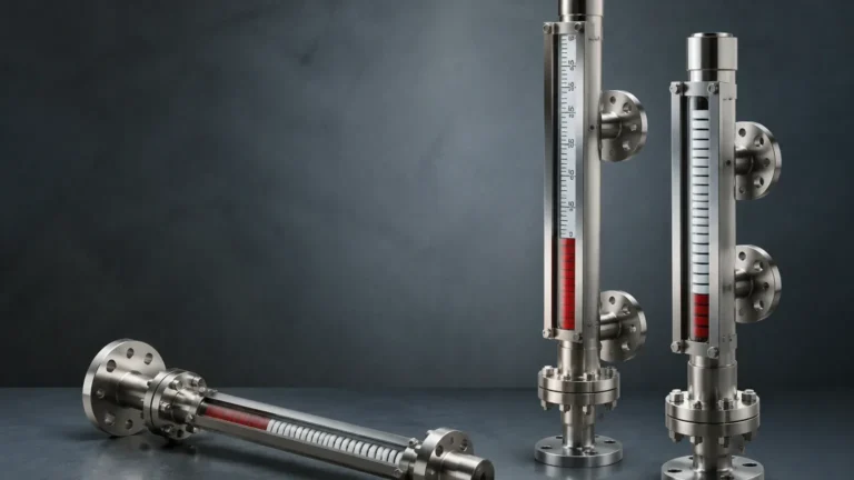
Magnetic level gauges consist of a bypass chamber mounted to the side of a vessel. Inside the chamber, a float containing a high-intensity magnet moves up and down with the liquid level. Outside the chamber, a column of interlocking magnetic flaps (or a magnetic capsule) reacts to the float's position, flipping to change color (usually from white to red or yellow).
Key Differences
* Visibility: RL gauges provide a direct view of the fluid, whereas magnetic gauges provide a mechanical representation. Magnetic gauges are often easier to read from a distance.
* Safety: Because magnetic gauges do not use glass in direct contact with the process fluid, they are generally considered safer for high-pressure (above 100 bar / 1450 psi) or highly toxic applications where glass failure would be catastrophic.
* Maintenance: RL gauges require periodic cleaning of the glass prisms to maintain contrast. Magnetic gauges are virtually maintenance-free unless the fluid is prone to scaling or magnetic particles (magnetite) are present.
Key Selection Criteria for Industrial Applications
When specifying an rl gauge for a project, several technical parameters must be confirmed to ensure the instrument's longevity and accuracy.
1. Pressure and Temperature Ratings
The mechanical integrity of the gauge body and the glass is paramount. Standard reflex gauges are typically rated for pressures up to 40 bar (580 psi) or 64 bar (928 psi), depending on the body material and thickness. For high-temperature steam applications, the glass must be protected or specifically treated to prevent erosion. In temperatures exceeding 250°C (482°F), the thermal expansion of the metal body must be accounted for to prevent glass breakage.
2. Material Compatibility
The "wetted parts" of the gauge—the components that touch the liquid—must be resistant to corrosion. Common materials include:
* Carbon Steel: Suitable for non-corrosive oils and hydrocarbons.
* 316/316L Stainless Steel: The industry standard for water treatment, chemicals, and food processing.
* Special Alloys (Monel, Hastelloy): Required for highly aggressive media like hydrofluoric acid or hot brine.
3. Connection Type and Center-to-Center Distance
The gauge must match the existing vessel nozzles. Common connections include flanged (ANSI, DIN, or JIS) or NPT/BSP threaded connections. The "Center-to-Center" (C-C) distance is the measurement between the centers of the top and bottom process connections. If the required C-C distance exceeds the maximum length of a single glass section (typically around 340 mm / 13.4 in), a multi-section gauge is used.
Technical Specifications and Selection Table
The following table provides a general comparison of common local level gauging technologies to assist in the initial selection process.
| Feature | Reflex (RL) Gauge | Transparent Gauge | Magnetic Level Gauge |
| :— | :— | :— | :— |
| Measurement Principle | Light Refraction | Direct Visual | Magnetic Float |
| Contrast | High (Black/Silver) | Low (Needs Illuminator) | High (Color Flaps) |
| Max Pressure (Typical) | 64 bar (928 psi) | 250 bar (3625 psi) | 400+ bar (5800+ psi) |
| Max Temp (Typical) | 400°C (752°F) | 400°C (752°F) | 530°C (986°F) |
| Interface Measurement | No | Yes | Yes |
| Steam Applications | Up to 35 bar (Saturated) | Excellent (with Mica) | Good |
| Visibility Distance | Moderate | Low | Excellent |

Installation and Commissioning Best Practices
Correct installation is critical to the performance of an rl gauge. Improper mounting can lead to leaks, glass stress, or inaccurate readings.
Orientation and Support
RL gauges must be installed perfectly vertical. If the gauge is tilted, the float (in magnetic types) may bind, or the prism effect in reflex types may be distorted. For long, multi-section gauges, additional support brackets should be attached to the vessel to prevent vibration-induced fatigue on the nozzles.
Isolation Valves
Every rl gauge should be installed with isolation valves (offset valves are preferred). These valves allow the gauge to be removed for maintenance without depressurizing the entire vessel. Offset valves are particularly useful because they allow a cleaning brush to be passed through the gauge chamber without removing the valve body. Many industrial standards also require "Auto-Ball Check" valves, which automatically shut off the flow if the gauge glass breaks.
Torque Requirements
During commissioning or after replacing a glass section, the bolts must be tightened in a specific sequence (usually a star pattern) to ensure even pressure on the gasket. Over-tightening can crack the glass, while under-tightening will lead to leaks once the system is pressurized. Always refer to the manufacturer’s torque specifications, which typically vary based on the gasket material (e.g., graphite vs. PTFE).
Operational Limitations and Safety Considerations
While the rl gauge is a robust instrument, it has limitations that engineers must recognize:
* Glass Erosion: In high-pressure steam service, the alkaline nature of the condensate can dissolve the silica in the glass. This thins the glass over time, eventually leading to failure. For steam pressures above 35 bar, transparent gauges with mica shields are often preferred over reflex gauges.
* Thermal Shock: Rapidly introducing a hot fluid into a cold gauge can cause the glass to shatter. Gauges should be pre-heated slowly by cracking the isolation valves open slightly before full operation.
* Coating and Fouling: If the process fluid leaves a residue or film on the glass, the prism effect will be lost. In such cases, the gauge will need frequent disassembly and cleaning.
Maintenance and Troubleshooting
Maintenance of an rl gauge primarily involves inspecting the glass and replacing seals.
1. Visual Inspection: Regularly check for "clouding" or scratching of the glass. Any sign of thinning or deep scratches is a signal to replace the glass immediately.
2. Leak Detection: Check for leaks around the cushion and sealing gaskets. Small leaks in steam service can lead to rapid erosion of the metal seating surface (wire-drawing), which may require the entire gauge body to be re-machined.
3. Cleaning: Use only soft cloths and compatible solvents to clean the prisms. Abrasive cleaners will destroy the prism edges and ruin the contrast effect.
Frequently Asked Questions (FAQs)
Q: Can an rl gauge be used for oil-water interface detection?
A: No. Because the reflex principle relies on the difference between gas and liquid, it cannot distinguish between two different liquid phases. A transparent gauge or a magnetic level gauge with a weighted float is required for interface applications.
Q: What is the purpose of a mica shield?
A: Mica shields are used in transparent gauges to protect the glass from the corrosive effects of high-pressure steam and hot alkaline solutions. They are not used in reflex gauges because the mica would block the prisms.
Q: How do I choose between a reflex gauge and a magnetic level gauge?
A: Choose a reflex rl gauge for cost-effective, direct visual monitoring of clean, non-hazardous liquids at moderate pressures. Choose Magnetic & Local Level Gauges for high-pressure, high-temperature, or toxic services where visibility from a distance and maximum safety are the priorities.
Q: What is the maximum length for a single rl gauge?
A: Individual glass sections are limited by manufacturing constraints, usually around 340 mm. For longer ranges, multiple sections are joined in a single staggered or continuous gauge body to cover the required span.
By adhering to these engineering principles and selection criteria, facilities can ensure that their level measurement systems provide the reliable, real-time data necessary for safe and efficient industrial operations.