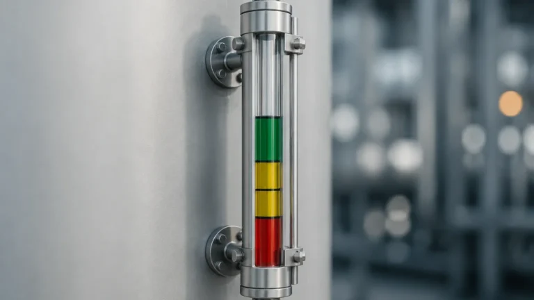
What Does Level Gauge Mean
What Does Level Gauge Mean
In the context of industrial process control and storage, understanding what does level gauge mean requires looking beyond a simple dictionary definition. A level gauge is a specialized instrument designed to provide a direct, local visual indication of the liquid level within a tank, pressure vessel, or piping system. Unlike level transmitters, which convert measurements into electronic signals (such as 4-20mA or HART) for remote monitoring in a control room, a level gauge is primarily intended for field operators to verify the contents of a vessel on-site.
The term "gauge" implies a physical measurement device that offers a reference point for manual inspection. In modern engineering, Magnetic & Local Level Gauges represent the evolution of this technology, moving from simple glass tubes to robust, magnetically coupled systems that enhance safety and reliability in hazardous environments.
Measurement Principles of Level Gauges
To understand the function of these instruments, one must first understand the physical principles they employ. Most local level gauges operate based on one of two fundamental concepts: the principle of communicating vessels or the principle of buoyancy.
The Principle of Communicating Vessels
This is the most basic form of level measurement, often seen in sight glasses or tubular gauges. Based on hydrostatic pressure, if two or more vessels containing a liquid are connected at the bottom, the liquid will reach the same height in all vessels, provided the pressure above the liquid surfaces is identical. By attaching a transparent tube to the side of a tank, the liquid level in the tube mimics the level inside the tank, allowing for direct visual confirmation.
The Principle of Buoyancy and Magnetic Coupling
In more advanced systems, such as magnetic level gauges, the measurement relies on Archimedes' principle. A float, specifically engineered to be lighter than the process liquid, sits on the surface of the fluid. Inside this float is a permanent magnet assembly. As the liquid level rises or falls, the float moves within a bypass chamber (a standpipe mounted to the side of the vessel).
Outside the chamber, an indicator—typically consisting of a series of bi-color magnetic flags or rollers—is mounted. The magnetic field from the float penetrates the chamber wall (which is made of non-magnetic material like 316 Stainless Steel) and flips the flags. This provides a clear, high-contrast visual representation of the level without the need for the process fluid to ever come into contact with the viewing glass or the operator.
Types of Local Level Gauges
Choosing the right instrument requires distinguishing between the various technologies available. While they all answer the question of "how much liquid is in the tank," they do so with different levels of safety and durability.
1. Tubular Level Gauges: The simplest form, consisting of a glass or plastic tube connected to the vessel. These are generally limited to low-pressure, non-toxic applications due to the risk of glass breakage.
2. Reflex Level Gauges: These use a prismatic glass that utilizes light refraction. The liquid-filled area appears dark, while the gas/vapor space appears bright. This provides a clear line of demarcation for colorless liquids.
3. Transparent Level Gauges: Featuring two pieces of flat glass on either side of the liquid column. These are used when the interface between two liquids must be observed or when the color of the liquid is important.
4. Magnetic Level Gauges: These are the preferred choice for high-pressure, high-temperature, or toxic media. Since the process is entirely contained within a metal pressure chamber, there is no risk of glass failure or leaks affecting the visibility of the gauge.
Technical Selection Criteria for Level Gauges
When specifying a level gauge for a project, engineers must evaluate several technical parameters to ensure the device performs accurately and safely. The following table outlines the key considerations for common local level gauge types.
| Feature | Tubular Gauge | Reflex/Transparent Gauge | Magnetic Level Gauge |
| :— | :— | :— | :— |
| Max Pressure | Up to 10 bar (1 MPa) | Up to 250 bar (25 MPa) | Up to 400 bar (40 MPa) |
| Max Temperature | Up to 100°C | Up to 400°C | Up to 530°C |
| Visibility | Moderate | High (Contrast-based) | Excellent (Bi-color flags) |
| Safety Level | Low (Glass risk) | Moderate | High (Total containment) |
| Maintenance | High (Cleaning glass) | Moderate (Gasket checks) | Low (Self-cleaning floats) |
| Interface Detection | No | Yes (Transparent only) | Yes (Specific float SG) |
Specific Gravity (SG) and Float Design
For magnetic gauges, the specific gravity of the liquid is the most critical factor. The float must be designed to displace enough liquid to remain buoyant. If the liquid has a low SG (e.g., 0.5 for liquefied gases), the float must be larger or made of lighter materials like Titanium to ensure it does not sink. Conversely, for high-pressure applications, the float must be structurally reinforced to prevent collapse, which in turn increases its weight and requires a larger diameter chamber.
Installation and Commissioning Considerations
Correct installation is vital for the accuracy of a level gauge. Because these are mechanical devices relying on gravity and magnetism, alignment and positioning are paramount.
* Vertical Alignment: The gauge must be installed perfectly vertical. Even a slight tilt can cause the internal float to rub against the chamber walls, leading to friction that prevents the float from following the liquid level accurately.
* Isolation Valves: It is standard engineering practice to install isolation valves (ball or globe valves) between the vessel and the gauge. This allows for maintenance or replacement without depressurizing the entire tank.
* Venting and Draining: Every gauge should be equipped with a vent plug at the top and a drain valve at the bottom. This allows operators to clear the chamber of trapped gas or sediment. In steam applications, regular "blow-down" of the gauge is necessary to prevent the buildup of scale.
* Center-to-Center Distance: This refers to the distance between the two process connections. Accurate measurement of this distance (in millimeters) is required during the procurement phase to ensure the gauge fits the existing tank nozzles.

Limitations and Operational Risks
While level gauges are highly reliable, they are not without limitations. Engineers must be aware of the following risks:
* Magnetic Interference: For magnetic gauges, the presence of external magnetic fields or nearby large ferrous structures can interfere with the coupling between the float and the indicator.
* Fouling and Scaling: If the process fluid is prone to crystallization or contains heavy solids, the float may become stuck. In such cases, a bypass chamber with a larger diameter or a specialized coating (like PTFE) may be required.
* Vibration: High levels of mechanical vibration in a plant can cause the magnetic flags to flip prematurely or settle in an incorrect position. High-quality gauges use "dampened" flags or magnetic locking mechanisms to prevent this.
* Flash Vaporization: In high-temperature applications, if the pressure drops suddenly, the liquid inside the gauge may boil (flash). This creates turbulence that can bounce the float violently, potentially damaging the internal components.
Maintenance and Troubleshooting
A proactive maintenance schedule ensures that the level gauge remains a dependable safety backup. For glass-based gauges, this involves inspecting for "thinning" of the glass caused by chemical erosion. For magnetic gauges, maintenance is simpler but still necessary.
1. Float Inspection: Periodically remove the float to check for buildup or signs of pitting/corrosion.
2. Chamber Flushing: Use the drain valve to flush out any accumulated sludge at the bottom of the bypass chamber.
3. Indicator Calibration: Ensure the zero point of the indicator scale aligns with the bottom process connection of the vessel.
Frequently Asked Questions (FAQ)
Q: Can a level gauge be used for remote monitoring?
A: Yes. While the primary function is local indication, magnetic level gauges can be fitted with reed switches (for point level alarms) or magnetostrictive transmitters (for continuous 4-20mA output) mounted to the outside of the chamber.
Q: What is the difference between a level gauge and a level glass?
A: A "level glass" (or sight glass) is a specific type of level gauge that uses transparent glass for direct viewing. "Level gauge" is a broader term that encompasses both glass-based and magnetic-based local indicators.
Q: Why choose a magnetic level gauge over a traditional sight glass?
A: Safety is the primary reason. If a sight glass breaks, the process fluid is released into the environment. A magnetic level gauge contains the fluid within a metal pressure pipe, making it much safer for high-pressure, toxic, or flammable liquids.
Q: Does the color of the liquid matter for a magnetic level gauge?
A: No. Because the indicator is external and coupled magnetically, the opacity or color of the liquid has no impact on the readability of the gauge.
Q: What is the maximum length of a level gauge?
A: Standard gauges are typically manufactured in lengths up to 6 meters. For taller tanks, gauges can be manufactured in sections and joined with flanges to cover the full height required.
By understanding what does level gauge mean in an operational context, facilities can better select the appropriate technology to balance cost, visibility, and process safety. Whether it is a simple tubular indicator for a water tank or a high-pressure magnetic gauge for a chemical reactor, these instruments remain a cornerstone of industrial field instrumentation.