Z Dimension Gauge
Z Dimension Gauge
In the field of industrial process control, the accuracy of liquid level measurement depends not only on the sensor technology used but also on the physical configuration of the instrument housing. For engineers working with Magnetic & Local Level Gauges, understanding the "Z dimension" is critical for ensuring that the instrument performs correctly across the entire measurement range.
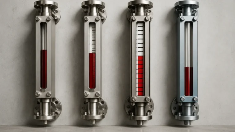
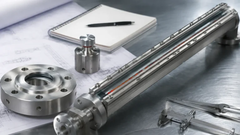
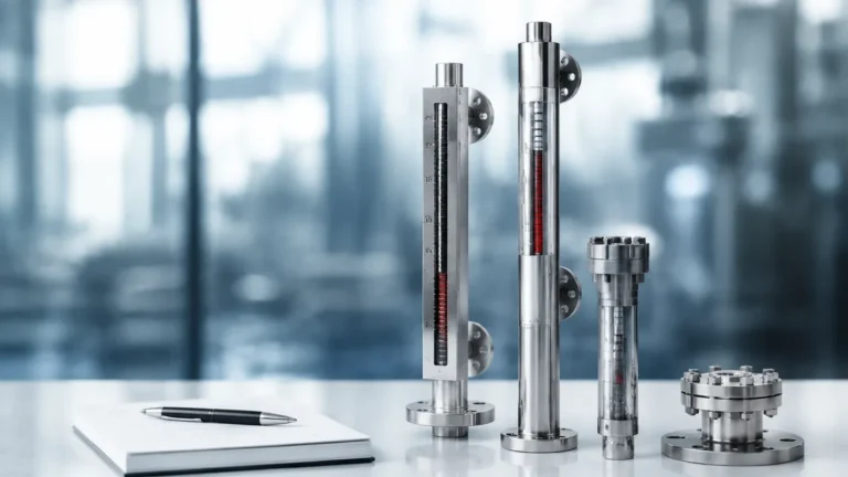
A z dimension gauge configuration refers to the specific engineering design of a magnetic level gauge (MLG) chamber, specifically the distance from the center of the bottom process connection to the bottom of the chamber. This dimension is essential for accommodating the float, which is the primary sensing element in these systems. Without a correctly calculated Z dimension, a gauge may fail to indicate the lowest levels of a liquid or, in worse cases, the float may obstruct the process piping.
Measurement Principles of Magnetic Level Gauges
Before detailing the specifics of the Z dimension, it is necessary to understand how a magnetic level gauge operates. These instruments function based on three fundamental physical principles: buoyancy, magnetism, and the law of communicating vessels.
The Law of Communicating Vessels
The gauge consists of a vertical chamber bypass-mounted to the side of a process vessel. According to the law of communicating vessels, the liquid level in the chamber will always be equal to the liquid level in the main tank. This allows for a representative measurement of the tank's contents within an isolated column.
Buoyancy and the Float
Inside the chamber is a float specifically engineered to match the specific gravity (SG) of the process fluid. Based on Archimedes' principle, the float displaces a volume of fluid equal to its own weight, allowing it to remain partially submerged at the liquid's surface. As the liquid level rises or falls, the float moves accordingly within the chamber.
Magnetic Coupling and Indication
The float contains an internal assembly of high-intensity magnets. Outside the chamber, a visual indicator—typically consisting of a series of bi-color magnetic flaps or a magnetic follower—is mounted. The magnetic field from the float penetrates the non-magnetic chamber wall (usually stainless steel or alloy), causing the flaps to rotate or the follower to move. This provides a clear, high-visibility local reading of the level without the need for glass windows or direct contact with the process fluid.
Defining the Z Dimension in Gauge Design
The Z dimension is a specialized term used in the design and ordering of magnetic level gauges. It represents the "dead zone" at the bottom of the gauge chamber. Specifically, it is the distance from the centerline of the bottom process connection to the bottom of the chamber cap.
Why the Z Dimension is Necessary
The float in a magnetic level gauge has a finite length, often ranging from 150 mm to over 500 mm depending on the pressure rating and fluid density. For the gauge to accurately show a "zero" or "empty" reading, the magnet inside the float must be able to descend to the zero point on the external scale.
If the chamber ended exactly at the bottom process connection, the float would hit the bottom of the pipe while its magnetic center was still significantly above the zero mark. Therefore, the chamber must be extended downward. This extension is the Z dimension. It provides the necessary clearance for the float to rest below the process connection when the tank is empty, ensuring the magnet aligns perfectly with the bottom of the visual indicator.
Engineering Selection for Z Dimension Gauges
Selecting the correct z dimension gauge configuration requires precise data regarding the process fluid and the operating environment. Welk engineers typically determine the Z dimension based on the following factors:
1. Fluid Specific Gravity (SG): This is the most critical factor. Fluids with low density (such as LPG or ammonia) require larger, more buoyant floats. A longer float necessitates a longer Z dimension to allow it to submerge and rest properly.
2. Operating Pressure: Higher pressures require floats with thicker walls to prevent collapse. Thicker walls increase the float's weight, which in turn requires a longer float body to maintain buoyancy, thus increasing the required Z dimension.
3. Operating Temperature: Temperature affects both the density of the fluid and the magnetic strength of the float. High-temperature applications may require specialized float materials that influence the overall length of the unit.
4. Bottom Connection Type: Whether the connection is a flange, a threaded NPT, or a socket weld will influence the physical layout of the bottom of the chamber.
Typical Z Dimension Requirements
| Fluid Specific Gravity (SG) | Typical Float Length | Recommended Z Dimension |
| :— | :— | :— |
| > 1.0 (Water/Brine) | 150 mm – 200 mm | 200 mm – 250 mm |
| 0.7 – 0.9 (Oil/Fuel) | 250 mm – 350 mm | 300 mm – 400 mm |
| 0.4 – 0.6 (LPG/Light Hydrocarbons) | 450 mm – 600 mm | 500 mm – 650 mm |
*Note: These are general estimates. Exact dimensions must be calculated based on the specific float model and pressure rating.*
Installation Considerations and Clearance
When installing a magnetic level gauge, the Z dimension must be accounted for in the plant's spatial layout. Because the chamber extends below the bottom process nozzle, there must be sufficient physical clearance beneath the gauge.
Vertical Alignment and Support
The gauge must be installed perfectly vertical to ensure the float can move freely without friction against the chamber walls. If the Z dimension is particularly long (e.g., in low-density applications), additional support brackets may be required at the bottom of the chamber to prevent vibration or mechanical stress on the process nozzles.
Nozzle Spacing (C-C Distance)
The Center-to-Center (C-C) distance refers to the distance between the top and bottom process nozzles. While the C-C distance defines the visible measuring range, the "Total Length" of the gauge is the C-C distance plus the Z dimension at the bottom and the "X dimension" (the extension at the top). Engineers must ensure that floor-level obstructions, structural beams, or other piping do not interfere with the Z dimension extension.
Maintenance Access
Magnetic level gauges occasionally require maintenance, such as cleaning the chamber of debris or inspecting the float. Most Z dimension designs include a drain plug or a flange at the very bottom. Installers should ensure there is enough room to remove the bottom flange and extract the float for inspection without decommissioning the entire gauge assembly.
Limitations and Critical Risks
While magnetic level gauges are robust, improper consideration of the Z dimension can lead to several operational risks:
* Inaccurate Zero Reading: If the Z dimension is too short, the float will hit the bottom of the chamber before the magnet reaches the zero point on the scale. The gauge will show a false level (e.g., 5% full) even when the tank is completely empty.
* Process Blockage: If the float is too long for the provided Z dimension, it may partially block the bottom process connection. This can lead to a "lag" in measurement as fluid cannot flow freely between the tank and the chamber.
* Float Damage: In high-turbulence applications, a float that is not properly seated in a correctly sized Z-space may be subject to mechanical wear or impact damage against the bottom cap.
* Coating and Buildup: In applications with viscous fluids or solids, the Z-dimension area can act as a collection point for sediment. Regular flushing via the drain connection is necessary to prevent the float from becoming stuck in the sediment at the bottom of the chamber.
Frequently Asked Questions
Q: Can I change the Z dimension after the gauge is manufactured?
A: No. The Z dimension is a structural part of the welded stainless steel chamber. It is determined during the engineering phase. If a process fluid changes to a lower density, a new float and potentially a new chamber with a larger Z dimension will be required.
Q: Does the Z dimension affect the accuracy of the gauge?
A: Indirectly, yes. While the accuracy is determined by the float's position relative to the liquid, an insufficient Z dimension prevents the gauge from accurately displaying the lowest levels of the tank.
Q: Is there a standard Z dimension for all gauges?
A: While many manufacturers have "standard" dimensions (e.g., 250 mm), Welk recommends custom calculations for every application to ensure the float length is perfectly matched to the fluid's specific gravity and pressure requirements.
Q: What is the "X dimension" compared to the Z dimension?
A: The X dimension is the extension at the top of the chamber (above the top process connection). It provides space for the float to rise above the maximum liquid level so that the magnet can reach the 100% mark on the scale. Like the Z dimension, it is essential for full-range measurement.
For more technical guidance on selecting the appropriate chamber configurations and float types for your specific industrial application, please consult our engineering team or review product options and application support to ensure your level measurement system is optimized for accuracy and safety.