4…20 Ma
4…20 Ma
In the landscape of industrial automation and process control, the 4…20 mA current loop remains the most prevalent analog signaling standard. Despite the rise of digital fieldbus protocols and wireless technologies, the reliability, simplicity, and noise immunity of the current loop make it the go-to choice for level measurement applications. For engineers and facility managers, understanding how to implement and maintain these signals is essential for ensuring accurate data transmission from the field to the control room.
Understanding the 4…20 mA Current Loop in Level Measurement
The 4…20 mA signal is an analog standard where a continuous current represents a process variable—in this case, the level of a liquid or solid in a tank or vessel. The range is defined by a "live zero" at 4 mA and a full-scale value at 20 mA. This 16 mA span is linearly proportional to the measurement range of the sensor.
One of the primary reasons for the 4 mA offset (rather than a 0…20 mA range) is fault detection. If a wire breaks or a sensor loses power, the current drops to 0 mA. Since 4 mA represents the minimum level (0%), a reading of 0 mA immediately alerts the control system to a loop failure. Furthermore, the 4 mA base current provides enough power to operate the internal electronics of a "2-wire" transmitter, eliminating the need for a separate power supply at the measurement point.
In level measurement, this signal is used to communicate the distance, height, or volume of the medium. For example, in a 10-meter (32.8 ft) tank, 4 mA would indicate an empty tank, 12 mA would indicate a half-full tank (5 meters / 16.4 ft), and 20 mA would indicate a completely full tank.
Measurement Principles: From Physical Level to Analog Signal
Before a 4…20 mA signal can be transmitted, the level meter must first convert a physical property into an electrical value. Different technologies achieve this through various physical principles. On the Main Page of industrial instrumentation providers like Welk, you will find several categories of sensors that utilize these principles.
1. Radar Level Measurement
Radar level meters (both guided wave and non-contact) use Time of Flight (ToF) principles. The sensor emits an electromagnetic pulse that reflects off the surface of the medium. The time it takes for the pulse to return is measured. The internal microprocessor calculates the distance based on the speed of light and then scales this value to a corresponding 4…20 mA output.
2. Ultrasonic Level Sensors
Similar to radar, ultrasonic sensors use ToF but rely on sound waves. These are ideal for atmospheric tanks. The sensor measures the time interval between the emission of an ultrasonic pulse and the reception of its echo. Because the speed of sound varies with temperature, these sensors often include a temperature probe to compensate the signal before outputting the 4…20 mA value.
3. Hydrostatic Level Transmitters
Hydrostatic sensors measure the pressure exerted by the liquid column above the sensor diaphragm. This pressure is directly proportional to the height of the liquid (P = ρgh). The pressure transducer converts this mechanical force into an electrical signal, which is then conditioned into a 4…20 mA loop.
4. Magnetic Level Gauges with Transmitters
Magnetic level gauges provide local visual indication via a float. To provide a remote 4…20 mA signal, a reed switch or magnetostrictive sensing rod is mounted to the side of the gauge. As the float moves, the electronics detect its position and output the standard current signal.
Selection Criteria for 4…20 mA Level Transmitters
Choosing the right instrument involves matching the measurement technology with the specific properties of the medium and the environment. The following table provides a comparison of common 4…20 mA level measurement technologies:
| Technology | Typical Accuracy | Media Suitability | Pressure/Temp Limits | Best Use Case |
| :— | :— | :— | :— | :— |
| Radar | ±2 mm to ±5 mm | Liquids, solids, corrosive | High (up to 40 bar / 400°C) | Chemical tanks, tall silos |
| Ultrasonic | ±0.25% of range | Water, wastewater | Low (Atmospheric) | Open channels, sumps |
| Hydrostatic | ±0.1% to ±0.5% | Clear liquids, oils | Moderate | Deep wells, vented tanks |
| Magnetic | ±5 mm to ±10 mm | Clean liquids | High | Boilers, fuel storage |
When selecting a device, engineers must confirm the loop resistance of their control system. A 4…20 mA signal requires a power source (typically 24V DC). The total resistance of the wiring and the input card of the PLC (Programmable Logic Controller) must not exceed the transmitter's maximum load capacity, often referred to as the "loop budget."
Installation Best Practices and Wiring Configurations
Proper installation is critical to maintaining signal integrity over long distances. The 4…20 mA signal is inherently resistant to electromagnetic interference (EMI) because it is a low-impedance current loop rather than a high-impedance voltage signal. However, best practices must still be followed.
Wiring Types
* 2-Wire Configuration: The most common setup. The transmitter is powered by the same two wires that carry the 4…20 mA signal. This reduces wiring costs and complexity.
* 3-Wire/4-Wire Configuration: Used when the sensor requires more power than 4 mA can provide (e.g., heated sensors or high-power radar). These require separate wires for power and signal.
Cable Selection and Grounding
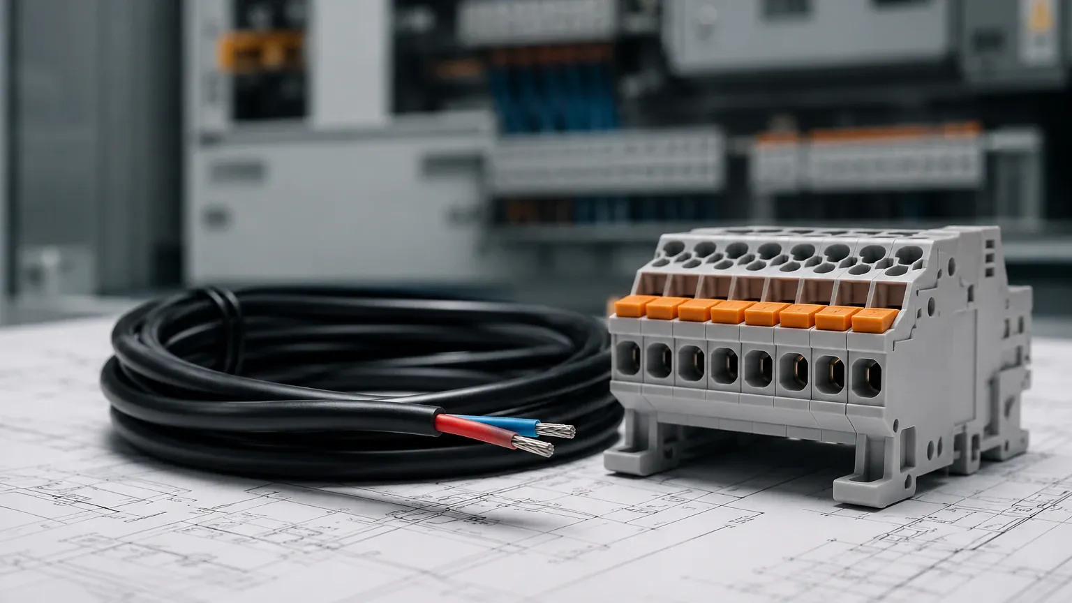
For most industrial applications, shielded twisted-pair cables are recommended. A cross-section of 0.5 mm² to 1.5 mm² (approx. 20 to 16 AWG) is standard. The shield should be grounded at only one end—typically at the control cabinet—to prevent ground loops, which can introduce significant errors into the 4…20 mA signal.
Installation Geometry
For non-contact sensors like radar or ultrasonic, the transmitter must be installed perpendicular to the liquid surface. Obstructions such as agitators, ladders, or inlet pipes can cause false echoes. Modern 4…20 mA transmitters often include "false echo suppression" software to ignore these fixed reflections, but proper physical placement remains the first line of defense against inaccurate readings.
Limitations and Troubleshooting 4…20 mA Systems
While robust, 4…20 mA systems are not without limitations. Understanding these challenges allows for more effective troubleshooting.
1. Loop Resistance: If the total resistance in the loop is too high, the transmitter will not be able to drive the full 20 mA current. This results in the signal "clipping" at a lower value, such as 18 mA, even when the tank is full. Engineers should calculate the maximum allowable resistance using Ohm's Law: $R_{max} = (V_{supply} – V_{min\_transmitter}) / 0.02$.
2. Signal Attenuation: Over extremely long distances (exceeding 1,000 meters / 3,280 feet), the resistance of the copper wire itself becomes significant. While current loops handle distance better than voltage signals, there is still a physical limit based on the power supply voltage.
3. Analog Resolution: A 4…20 mA signal is a continuous analog wave. When it reaches a PLC, it is converted into a digital value (e.g., 0 to 4095 for a 12-bit converter). The precision of the measurement is limited by the resolution of the A/D converter in the control system.
4. HART Protocol Integration: Many modern 4…20 mA level meters also support the HART (Highway Addressable Remote Transducer) protocol. This allows a digital signal to be superimposed on top of the analog 4…20 mA signal. It enables remote configuration and diagnostics without interrupting the primary analog measurement.
Frequently Asked Questions (FAQs)
Q: Why use 4…20 mA instead of 0…10V?
A: Voltage signals are susceptible to voltage drops over long wire runs and are highly sensitive to electromagnetic noise. Current loops maintain the same current throughout the entire loop regardless of wire resistance, making them more accurate for long-distance industrial applications.
Q: Can I use a 4…20 mA sensor in a hazardous area?
A: Yes, many 4…20 mA transmitters are designed to be "intrinsically safe." When used with a Zener barrier or galvanic isolator, the energy in the loop is limited to levels that cannot ignite explosive atmospheres.
Q: How do I calibrate a 4…20 mA level transmitter?
A: Calibration involves setting the "Lower Range Value" (LRV) to 4 mA and the "Upper Range Value" (URV) to 20 mA. This can be done using on-board buttons, a HART communicator, or specialized software. It is important to calibrate the sensor to the actual tank dimensions rather than the factory defaults.
Q: What happens if the polarity is reversed during wiring?
A: Most modern industrial transmitters include reverse polarity protection. The device simply will not power up or output a signal until the wiring is corrected, preventing damage to the internal circuitry.
For technical specifications and to explore various level measurement technologies that utilize the 4…20 mA standard, you may visit the Main Page for detailed product documentation and application support.