800 2500
800 2500
In the field of industrial process control, level measurement serves as a critical pillar for operational safety, inventory management, and environmental compliance. When engineers and facility managers evaluate instrumentation for specific vessel geometries—particularly those requiring a measurement span between 800 2500 mm (approximately 31.5 to 98.4 inches)—selecting the correct technology is paramount. This range is common in chemical dosing tanks, water treatment sumps, and medium-sized storage vessels across the oil, gas, and food processing industries.
Understanding the physics behind different measurement principles allows for a more informed selection process. Whether the application involves corrosive liquids, slurries, or volatile hydrocarbons, the choice between ultrasonic, radar, and hydrostatic technologies depends on the physical properties of the medium and the environmental conditions of the installation site.
Principles of Level Measurement Technology
Before selecting a device for a specific 800 2500 mm application, it is essential to understand how different sensors perceive the liquid surface. The three most common technologies used in this range are ultrasonic, radar, and hydrostatic pressure.
Ultrasonic Level Measurement
Ultrasonic sensors operate on the Time-of-Flight (ToF) principle. The sensor emits a high-frequency acoustic pulse that travels through the air, reflects off the surface of the liquid, and returns to the transducer. By measuring the time elapsed between emission and reception, and knowing the speed of sound in air, the device calculates the distance to the product surface.
For a range of 800 2500 mm, ultrasonic sensors are often the most cost-effective solution. However, they are sensitive to air temperature fluctuations, heavy foam, and vacuum conditions, as sound requires a medium (air or gas) to propagate.
Radar Level Measurement
Radar sensors also use the ToF principle but employ electromagnetic waves instead of sound. These waves travel at the speed of light. Radar is generally divided into two types: Guided Wave Radar (GWR), which uses a probe to direct the signal, and Non-Contact Radar, which broadcasts signals through the air.
Radar is highly effective in the 800 2500 mm range when the process involves high pressure, extreme temperatures, or vapors that would attenuate an ultrasonic signal. Because electromagnetic waves do not require a physical medium, they are unaffected by vacuum or changes in gas composition.
Hydrostatic Level Measurement
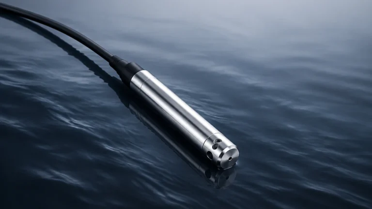
Hydrostatic transmitters measure the pressure exerted by a liquid column at a specific point. The relationship is defined by the formula: $P = \rho \cdot g \cdot h$, where $P$ is pressure, $\rho$ is the density of the liquid, $g$ is gravity, and $h$ is the height of the liquid. In a tank with a height between 800 2500 mm, a submersible or flange-mounted pressure transmitter provides a direct measurement of the liquid's weight above the sensor diaphragm.
Evaluating the 800 2500 mm Measurement Span
The 800 2500 mm range represents a "medium-short" span in industrial terms. It is long enough that simple point-level switches are insufficient for continuous monitoring, yet short enough that the "dead zone" or "blocking distance" of a sensor becomes a significant factor in the installation design.
The Importance of the Dead Zone
Every non-contact sensor has a minimum distance it cannot measure, known as the dead zone. For an ultrasonic sensor calibrated for an 800 2500 mm range, the dead zone might be 100 mm to 250 mm. If the tank is filled above this point, the sensor will lose accuracy or provide an error signal. Therefore, when designing a system for an 800 2500 mm span, the sensor must be mounted high enough to ensure the maximum liquid level never enters this zone.
Accuracy and Resolution
In a 2500 mm tank, a 0.25% accuracy rating translates to an error of $\pm 6.25$ mm. For many water treatment applications, this is perfectly acceptable. However, in high-value chemical blending, higher precision might be required. Radar sensors often provide better resolution in these scenarios compared to standard ultrasonic units.
Selection Criteria for 800 2500 mm Applications
Choosing the right instrument requires a systematic comparison of the process conditions against the sensor's capabilities. The following table provides a general guideline for selecting technology within the 800 2500 mm range.
| Feature | Ultrasonic | Radar (Non-Contact) | Hydrostatic |
| :— | :— | :— | :— |
| Optimal Range | 0.1m – 15m | 0.1m – 70m | 0m – 200m |
| Cost | Low to Medium | Medium to High | Medium |
| Effect of Foam | High Interference | Moderate Interference | No Effect |
| Effect of Vapor | High Interference | Negligible | No Effect |
| Installation | Top-mounted | Top-mounted | Bottom or Submerged |
| Maintenance | Low (No contact) | Low (No contact) | Moderate (Contact) |
| Density Changes | No Effect | No Effect | High Effect |
When reviewing specific hardware, engineers often consult the Main Page of a manufacturer's catalog to compare signal outputs (such as 4-20mA, HART, or Modbus) and ingress protection (IP) ratings suitable for the environment.
Installation Considerations and Best Practices
Proper installation is as important as selecting the right technology. For the 800 2500 mm span, several mechanical factors must be addressed to ensure reliable data.
1. Mounting Position: Sensors should be mounted away from the tank wall to avoid false reflections (in the case of radar and ultrasonic) and away from the fill inlet to avoid turbulence or signal interference from falling liquid.
2. Nozzle Height: If using a mounting nozzle, the nozzle must be short enough and wide enough that the sensor's beam angle does not hit the sides of the nozzle. This is particularly critical for ultrasonic sensors with wider beam angles.
3. Stilling Wells: In applications with high agitation or surface foam, a stilling well (a vertical pipe submerged in the liquid) can be used to provide a calm surface for the sensor to measure. This is a common solution for radar and ultrasonic sensors in the 800 2500 mm range.
4. Venting: For hydrostatic sensors in sealed tanks, a vented cable or a differential pressure transmitter is required to compensate for changes in atmospheric or headspace pressure. Without proper venting, the sensor will report an incorrect level as the pressure above the liquid changes.

Limitations and Common Risks
While the 800 2500 mm range is standard for many sensors, certain risks can lead to measurement failure if not properly mitigated.
* Condensation: In outdoor tanks or heated processes, moisture can condense on the transducer face of ultrasonic and radar sensors. While some sensors have "drip-off" designs, heavy condensation can still block the signal.
* Internal Obstructions: Ladders, agitator blades, and heating coils can create "ghost echoes." Modern digital sensors allow for "false echo suppression," where the software is programmed to ignore reflections from fixed internal structures.
* Liquid Density Fluctuations: Hydrostatic sensors are calibrated based on a specific liquid density. If the process involves different fluids or significant temperature swings that change the density, the level reading will drift unless a density-compensated system is used.
Practical Engineering Maintenance
To maintain accuracy over the life of the instrument, a regular maintenance schedule should be implemented. For non-contact sensors, this usually involves a visual inspection of the sensor face to ensure no buildup of solids or corrosive byproduct has occurred. For hydrostatic sensors, periodic recalibration or "zeroing" may be necessary to account for sensor drift over time.
In the 800 2500 mm range, sensors are often accessible without specialized climbing equipment, making routine maintenance relatively straightforward. However, if the medium is hazardous, the use of non-contact technology is preferred to minimize technician exposure during maintenance cycles.
Frequently Asked Questions (FAQ)
Q: Can I use an ultrasonic sensor for a 2500 mm tank containing sulfuric acid?
A: Yes, provided the sensor housing and transducer are made of chemically resistant materials like PVDF or PTFE. However, if the acid produces heavy fumes, radar may be a more reliable choice as fumes can slow down or absorb ultrasonic pulses.
Q: How does the beam angle affect my 800 2500 mm measurement?
A: The beam angle determines the "footprint" of the signal at the bottom of the tank. For a 2500 mm depth, a 10-degree beam angle will create a circle of approximately 440 mm at the bottom. You must ensure no obstructions (like pipes or pumps) fall within this circle.
Q: Is hydrostatic measurement better for turbulent liquids?
A: Generally, yes. Hydrostatic pressure is unaffected by surface turbulence or foam, making it an excellent choice for agitated tanks where ultrasonic or radar signals might be scattered.
Q: What is the benefit of a 4-20mA HART output in this range?
A: HART allows for digital communication over the standard analog wire. This enables remote configuration, diagnostics, and the ability to read multiple variables (like temperature and level) from a single device, which is highly beneficial for integrating the 800 2500 mm measurement into a broader SCADA or PLC system.
Conclusion
Successfully managing liquid levels in the 800 2500 mm range requires a balance of technology, environmental awareness, and mechanical precision. By understanding the fundamental principles of ultrasonic, radar, and hydrostatic measurement, and by adhering to strict installation guidelines, industrial operators can ensure accurate and reliable data. Whether the goal is to prevent tank overfills or to optimize chemical dosing, the right level measurement solution is the foundation of a safe and efficient process. For those looking to explore specific hardware options and technical specifications, visiting a dedicated resource like the Main Page provides the necessary detail to finalize an instrumentation strategy.