Analog Level Sensor
Analog Level Sensor
In modern industrial automation, the ability to monitor fluid or solid levels in real-time is critical for process efficiency, safety, and inventory management. An analog level sensor serves as the primary interface between the physical state of a medium and the control system, providing a continuous signal that represents the exact level within a vessel. Unlike point-level switches that only indicate whether a level has reached a specific threshold, analog sensors provide a graduated output, allowing operators to track trends, manage pump speeds, and prevent overflows or dry-run conditions with high precision.
For engineers and plant managers, selecting the correct analog level sensor requires a deep understanding of measurement principles, signal types, and the environmental variables that can affect accuracy. This guide provides a technical overview of analog level measurement technologies, selection criteria, and practical installation considerations for industrial applications.
Understanding the Role of Analog Signals in Level Measurement
The term "analog" refers to the nature of the output signal. In industrial instrumentation, the most common analog outputs are the 4-20 mA current loop and 0-10 V voltage signals.
The 4-20 mA Current Loop
The 4-20 mA standard is the preferred choice for industrial environments. In this configuration, 4 mA typically represents the 0% (empty) level, while 20 mA represents the 100% (full) level. This method is highly favored because current signals are inherently resistant to electromagnetic interference (EMI) and voltage drops over long cable runs. Furthermore, the "live zero" at 4 mA allows the control system to distinguish between a zero-level reading and a wire break; if the signal drops to 0 mA, the system immediately recognizes a fault.
0-10 V Voltage Signals
Voltage-based signals are simpler to integrate with certain types of Programmable Logic Controllers (PLCs) and microcontrollers. However, they are susceptible to voltage drops across long distances due to wire resistance and are more prone to noise in environments with heavy machinery. These are generally reserved for short-distance applications or controlled laboratory settings.
Core Measurement Principles for Analog Level Sensors
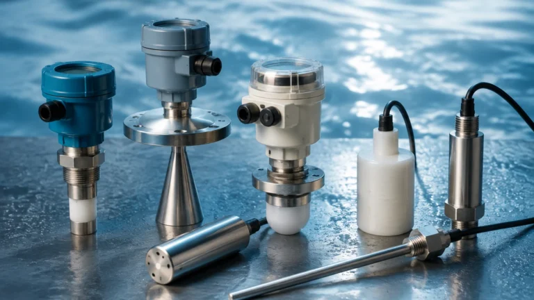
Analog level sensors utilize various physical principles to determine the distance to the surface of a material or the pressure exerted by a liquid column. Understanding these principles is the first step in selecting the right instrument from a professional manufacturer like Welk.
Radar (Time-of-Flight)
Radar level meters emit high-frequency electromagnetic waves (typically in the GHz range). These waves travel to the surface of the medium, reflect, and return to the sensor's antenna. The sensor calculates the distance based on the time it takes for the signal to travel (Time-of-Flight). Because radar waves do not require a medium for travel, they are unaffected by vacuum, high pressure, or temperature fluctuations.
Ultrasonic (Sound Wave Reflection)
Similar to radar, ultrasonic sensors use Time-of-Flight, but they employ high-frequency sound waves. The sensor emits an ultrasonic pulse that bounces off the surface of the liquid or solid. While cost-effective and non-contact, ultrasonic sensors are sensitive to air temperature, heavy foam, and dust, which can attenuate or distort the sound waves.
Hydrostatic (Pressure-Based)
Hydrostatic level transmitters measure the pressure exerted by a liquid column at a specific depth. Based on the principle that pressure is proportional to the height of the liquid and its density ($P = \rho gh$), the sensor converts this mechanical pressure into an analog signal. This is a contact-based method often used in deep wells, tanks, and water treatment facilities.
Magnetostrictive and Magnetic Gauges
These sensors use a float containing a magnet. In magnetostrictive sensors, an electromagnetic pulse is sent down a sensing wire. When the pulse meets the magnetic field of the float, a torsional wave is generated and travels back to the electronics. This provides extremely high accuracy (often sub-millimeter) for clean liquids in the chemical and oil and gas industries.
Comparing Analog Level Sensor Technologies
Choosing the right technology depends on the physical properties of the medium and the physical constraints of the installation site. Below is a comparison of the most common technologies used in industrial automation.
| Technology | Contact Type | Ideal Media | Accuracy | Typical Range |
| :— | :— | :— | :— | :— |
| Radar | Non-contact | Corrosive liquids, solids, high-temp | ±2 mm to ±5 mm | Up to 70m |
| Ultrasonic | Non-contact | Water, wastewater, mild chemicals | ±0.25% of range | 0.3m to 15m |
| Hydrostatic | Contact | Water, fuel, oils | ±0.1% to ±0.5% | 1m to 200m |
| Magnetostrictive| Contact | Clean fuels, liquefied gases | ±1 mm | 0.3m to 6m |
| Capacitance | Contact | Powders, non-conductive liquids | ±1% of range | 0.5m to 3m |
Practical Selection Criteria
When evaluating an analog level sensor for a specific project, engineers should confirm the following parameters before procurement:
1. Media Characteristics: Is the material liquid, solid, or slurry? Does it have a high dielectric constant (important for radar) or high density (important for hydrostatic)?
2. Process Conditions: What are the maximum and minimum operating temperatures and pressures? For example, standard ultrasonic sensors may fail if the temperature exceeds 80°C (176°F), whereas specialized radar units can handle over 250°C (482°F).
3. Vessel Geometry: Is the tank tall and narrow, or short and wide? Are there internal obstructions like agitators, ladders, or heating coils? Non-contact sensors like radar require a clear line of sight or advanced software to "mask" internal reflections.
4. Accuracy Requirements: Does the application require high-precision custody transfer (e.g., fuel sales) or simple process monitoring (e.g., wastewater sump control)?
5. Output Requirements: While 4-20 mA is standard, does the application require digital protocols like HART, Modbus, or Profibus overlaid on the analog signal for remote diagnostics?
For a comprehensive look at available hardware and technical specifications, you can Review product options and application support on the Welk Main Page.
Installation Guidelines and Best Practices
Proper installation is just as important as selecting the right sensor. Even the most advanced analog level sensor will provide inaccurate data if installed incorrectly.
Mounting Position
* Avoid the Center: For non-contact sensors (radar and ultrasonic) in cylindrical tanks, avoid mounting the sensor in the exact center of the tank roof. This can cause "multiple echoes" as the signal bounces off the curved walls and returns simultaneously.
* Stay Away from Inlets: Do not mount the sensor directly above the fill pipe. The turbulence and falling material will interfere with the signal and cause erratic readings.
* Dead Zone (Blocking Distance): Every ultrasonic and radar sensor has a "dead zone" directly beneath the transducer where it cannot measure. Ensure the sensor is mounted high enough that the maximum liquid level never enters this zone.
Wiring and Signal Integrity
* Shielded Cables: Use twisted-pair, shielded cabling for all 4-20 mA loops to minimize the impact of EMI from nearby motors or variable frequency drives (VFDs).
* Grounding: Ensure the shield is grounded at only one end (usually the PLC side) to prevent ground loops, which can introduce offsets into the analog signal.
* Power Supply: Verify that the power supply can handle the voltage drop of the loop, especially if using a 2-wire (loop-powered) transmitter over a long distance.
Calibration
Most modern analog sensors are calibrated using a "dry" or "wet" setup.
* Dry Calibration: Setting the 4 mA and 20 mA points via software or push-buttons based on calculated distances.
* Wet Calibration: Physically filling and emptying the tank to set the signal points based on actual levels. This is often more accurate for hydrostatic sensors where fluid density might vary slightly from theoretical values.
Operational Limitations and Environmental Factors
No single analog level sensor is universal. Each has limitations that must be managed:
* Vapor and Steam: Heavy steam can attenuate ultrasonic signals, leading to a loss of echo. Radar is generally immune to steam but can be affected by heavy condensation on the antenna lens.
* Foam: Surface foam acts as an absorber for sound and radio waves. While high-frequency radar can often penetrate light foam, thick protein-based foams may require a contact-based solution like a magnetic level gauge or a hydrostatic transmitter.
* Build-up: In applications involving sticky liquids or slurries, material can build up on the sensor face. Non-contact sensors are less prone to this, but even they may require periodic cleaning or the use of a PTFE-coated antenna to shed droplets.
* Atmospheric Pressure: Hydrostatic sensors measure relative pressure. If a tank is sealed and pressurized, a standard submersible pressure transducer will give a false reading unless a differential pressure transmitter is used to compensate for the headspace pressure.
Frequently Asked Questions (FAQs)
Q: Can I use an analog level sensor for solids like grain or sand?
A: Yes, but you must choose the right technology. Radar (specifically high-frequency FMCW radar) is excellent for solids. Ultrasonic can work but requires a tilting mounting flange to align the sensor with the angle of repose of the material.
Q: What is the maximum distance a 4-20 mA signal can travel?
A: Depending on the wire gauge and the power supply voltage, a 4-20 mA signal can typically travel 1,000 meters (approx. 3,280 feet) or more without significant signal degradation, provided there is no excessive EMI.
Q: How do I handle a tank with an agitator?
A: If using a non-contact sensor, look for units with "false echo suppression" software. This allows the sensor to learn the position of the agitator blades and ignore them. Alternatively, a bypass pipe (stilling well) can be installed to provide a calm surface for measurement.
Q: Is a 2-wire or 4-wire sensor better?
A: 2-wire (loop-powered) sensors are easier to install as they use the same two wires for power and signal. 4-wire sensors have separate power leads and are typically used for high-power devices like certain types of radar or units with integrated heaters for cold climates.
Conclusion
The integration of a reliable analog level sensor is a foundational step in optimizing industrial processes. By providing continuous, real-time data, these instruments enable precise control over inventory and production workflows. Whether utilizing the robustness of hydrostatic pressure or the advanced capabilities of non-contact radar, understanding the interaction between the sensor and the process environment is key to long-term operational success. For engineering teams looking to implement these solutions, focusing on signal integrity, correct mounting, and media compatibility will ensure the highest return on investment and system reliability.