API 2350 5th Edition Sil Requirements
API 2350 5th Edition Sil Requirements
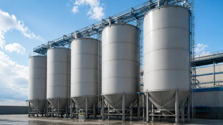
In the realm of industrial liquid storage, particularly within the petroleum and chemical sectors, overfill prevention is not merely a safety preference but a stringent regulatory and operational necessity. The American Petroleum Institute (API) Standard 2350, specifically the 5th edition, provides the definitive framework for preventing overfills in atmospheric storage tanks. A critical component of this standard is its alignment with functional safety standards, leading to specific API 2350 5th edition SIL requirements.
Understanding these requirements requires a deep dive into the intersection of risk management, instrumentation technology, and the lifecycle of Safety Instrumented Systems (SIS). For engineers and facility managers, the transition to the 5th edition represents a move from prescriptive hardware mandates to a risk-based approach that prioritizes Safety Integrity Levels (SIL).
Understanding the Core Principles of API 2350 5th Edition
API 2350 applies to atmospheric tanks at refineries, marketing terminals, and pipeline facilities. The 5th edition emphasizes the use of a Management System (MS) and a formal Risk Assessment (RA) to determine the necessary level of overfill protection.
The Shift to Functional Safety
One of the most significant changes in the 5th edition is the formalization of the relationship between overfill prevention and the IEC 61511 standard (Functional Safety – Safety Instrumented Systems for the Process Industry Sector). When a risk assessment determines that an Automatic Overfill Prevention System (AOPS) is required to reduce risk to a tolerable level, that system must be treated as a Safety Instrumented System (SIS). This is where SIL (Safety Integrity Level) becomes the primary metric for reliability.
Categories of Overfill Prevention Systems (OPS)
API 2350 defines three categories of systems based on the level of automation and human intervention:
1. Category 1 (Manual): Relies on personnel to monitor levels and manually terminate receipt. It requires a high-level alarm (HLA) independent of the tank gauging system.
2. Category 2 (Semi-Automatic): Includes an independent HLA that alerts personnel to take action, but also provides some level of automated response or enhanced signaling.
3. Category 3 (Automatic): An AOPS that automatically terminates the flow of liquid into the tank without human intervention when a high-high level (HHLA) is reached.
Under the 5th edition, if a Category 3 system is required by the risk assessment, it must meet the SIL requirements defined in the safety requirement specification (SRS).
Measurement Principles for Overfill Prevention
Before selecting hardware to meet API 2350 5th edition SIL requirements, it is essential to understand the measurement principles utilized in modern level instrumentation. Reliable overfill prevention starts with choosing the right physics for the specific media and environment.
Radar Level Measurement (Non-Contact)
Radar level meters, such as Frequency Modulated Continuous Wave (FMCW) or pulse radar, emit electromagnetic waves toward the liquid surface. The time-of-flight or frequency shift is used to calculate the distance.
* Advantages: No moving parts, highly accurate (often within ±1 mm), and unaffected by density changes or vapor space conditions.
* SIL Suitability: High-end radar units are frequently certified for SIL 2 or SIL 3 applications due to their internal diagnostics and high reliability.
Guided Wave Radar (GWR)
GWR utilizes a probe (cable or rod) to guide the microwave pulse to the liquid surface.
* Advantages: Excellent for low dielectric fluids and applications with turbulence or foam, as the probe concentrates the signal.
* SIL Suitability: Often used in redundant configurations to meet SIL 2 requirements in volatile hydrocarbon storage.
Ultrasonic Level Sensors
Ultrasonic sensors emit sound pulses that reflect off the liquid surface.
* Advantages: Cost-effective for water-based liquids and non-volatile chemicals.
* Limitations: Sound speed varies with temperature and pressure, and vapors can attenuate the signal. In petroleum applications, radar is generally preferred over ultrasonic for high-integrity overfill protection.
Point Level Switches
While continuous measurement is ideal for monitoring, point level switches (such as tuning forks or magnetic floats) are often used as the independent HHLA trigger in an AOPS.
* Tuning Fork Switches: Vibrate at a specific frequency; when immersed in liquid, the frequency shifts, triggering an alarm. These are robust and easily tested.
For a comprehensive look at hardware that supports these principles, engineers can Review product options and application support to ensure their selections align with current safety standards.
API 2350 5th Edition SIL Requirements and Risk Assessment
The determination of whether a system needs to be SIL 1, SIL 2, or SIL 3 is not dictated directly by API 2350 but is a result of the Layer of Protection Analysis (LOPA) or other risk assessment methodologies mandated by the standard.
The Role of SIL in Overfill Prevention
SIL is a measure of the Probability of Failure on Demand (PFD).
* SIL 1: PFD between 10⁻¹ and 10⁻². Usually sufficient for tanks with low turnover and lower environmental impact.
* SIL 2: PFD between 10⁻² and 10⁻³. Often required for large-scale petroleum storage where a spill would result in catastrophic fire or environmental damage.
* SIL 3: PFD between 10⁻³ and 10⁻⁴. Rarely required for atmospheric storage but may be seen in highly toxic or high-pressure chemical storage.
Independence and Redundancy
A core requirement of the 5th edition is the independence of the overfill prevention system. The sensor used for the AOPS or the HHLA must be physically and electrically separate from the Basic Process Control System (BPCS) used for routine tank gauging. To achieve higher SIL levels, redundancy (e.g., a 1oo2 or 2oo3 voting logic) is often implemented using different measurement technologies to avoid common-cause failures.
Technical Selection and Comparison Table
When designing a system to meet API 2350 5th edition SIL requirements, the following table provides a comparison of common technologies used in high-integrity overfill prevention.
| Technology | Measurement Principle | Typical SIL Capability | Ideal Application | Limitations |
| :— | :— | :— | :— | :— |
| 80GHz Radar | Non-contact FMCW | SIL 2 / SIL 3 | High-accuracy petroleum storage | Requires clear line of sight |
| Guided Wave Radar | Contact Microwave | SIL 2 | Low dielectric liquids, small tanks | Probe can accumulate buildup |
| Tuning Fork | Vibrating Frequency | SIL 2 / SIL 3 | Independent HHLA switch | Point level only; no continuous data |
| Hydrostatic | Pressure-based | SIL 1 / SIL 2 | Constant density liquids | Sensitive to density changes |
| Magnetic Gauge | Float/Magnetic | SIL 1 | Visual confirmation + switch | Moving parts subject to wear |
Installation and Commissioning Considerations
Meeting SIL requirements involves more than just buying a certified device. The installation must adhere to the Safety Requirement Specification (SRS).
1. Mounting Position: Sensors must be positioned to avoid internal tank obstructions like agitators, heating coils, or ladders. For radar, the "dead zone" or "blocking distance" at the top of the tank must be accounted for to ensure the HHLA triggers before the liquid reaches the tank roof.
2. Environmental Shielding: While radar is robust, extreme temperatures may require sunshades or cooling jackets for the electronics to maintain the calculated Mean Time Between Failures (MTBF).
3. Electrical Isolation: Wiring for the SIL-rated loop must be kept separate from non-safety wiring to prevent interference and accidental bypass.

Maintenance and Proof Testing: The Lifecycle Approach
One of the most rigorous aspects of API 2350 5th edition is the emphasis on the full lifecycle of the safety system. A SIL rating is only valid if the system is maintained and tested according to its design.
Proof Testing
Proof testing is a periodic test performed to detect dangerous hidden failures in a SIS. The 5th edition requires that the interval for proof testing be defined based on the required PFD.
* Partial Proof Test: Can often be done remotely via software diagnostics (e.g., checking the electronics and signal strength).
* Full Proof Test: Requires physically raising the liquid level or using a test lever/magnet to verify the sensor, logic solver, and final control element (e.g., an emergency shutdown valve) all function correctly.
Documentation
Under the 5th edition, every overfill event, near miss, and maintenance activity must be documented. This data is used to verify that the actual performance of the system matches the assumptions made during the initial risk assessment.
Limitations and Common Risks in Implementation
Despite the advancements in technology, certain risks can compromise a SIL-rated overfill prevention system:
* Common-Cause Failure: Using two identical sensors from the same manufacturer for redundancy can lead to both failing simultaneously due to a shared software bug or environmental condition.
* Bypassing Safeties: Operational pressure may lead personnel to bypass alarms or interlocks. API 2350 requires administrative controls to prevent unauthorized bypassing.
* Inadequate Response Time: The system must be designed so that the time between the HHLA trigger and the actual cessation of flow (including valve closing time) is shorter than the time it takes for the tank to reach its critical high level.
Frequently Asked Questions (FAQs)
Q: Does every tank need a SIL 2 rated system under API 2350 5th Edition?
A: No. The required SIL is determined by a risk assessment. Some tanks may only require Category 1 (manual) or Category 2 systems, which do not necessarily fall under the full IEC 61511 SIS requirements.
Q: Can I use my existing tank gauge for overfill prevention?
A: Generally, no. API 2350 requires the overfill prevention sensor to be independent of the tank gauging system used for inventory management to ensure that a single failure doesn't disable both monitoring and protection.
Q: What is the difference between a "Safe" failure and a "Dangerous" failure?
A: A safe failure results in a nuisance alarm or a shutdown when no overfill is occurring. A dangerous failure is one that prevents the system from responding when an actual overfill occurs. SIL ratings focus primarily on reducing the probability of dangerous failures.
Conclusion
Adhering to API 2350 5th edition SIL requirements is a multi-disciplinary effort that combines process safety, mechanical engineering, and advanced instrumentation. By transitioning to a risk-based methodology, facilities can ensure that their investment in safety hardware is proportional to the actual hazards present. Whether utilizing non-contact radar for continuous monitoring or robust tuning forks for independent high-level switching, the goal remains the same: the total prevention of hazardous overfills through reliable, verifiable, and independent safety layers.