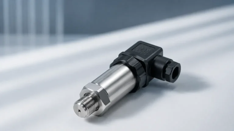
Biomass Sensor
Biomass Sensor
In the transition toward renewable energy, biomass has emerged as a critical fuel source for power plants, industrial boilers, and district heating systems. However, managing biomass—which ranges from wood pellets and chips to agricultural residues and processed waste—presents unique challenges for inventory management. A biomass sensor is an essential component in these systems, ensuring that silos, hoppers, and bunkers maintain optimal levels to prevent process interruptions.
This guide explores the engineering principles behind biomass level measurement, the technologies available, and the practical considerations for selecting and installing these sensors in demanding industrial environments.
Understanding Biomass Level Measurement Principles
Before selecting a biomass sensor, it is necessary to understand how different technologies interact with the physical properties of biomass materials. Unlike liquids, biomass solids are often non-homogeneous, dusty, and prone to forming irregular surfaces.
Time-of-Flight (ToF) Principle
Most continuous biomass sensors operate on the Time-of-Flight principle. The sensor emits a signal (either electromagnetic waves or sound waves) that travels to the surface of the material, reflects, and returns to the sensor. By measuring the time elapsed, the device calculates the distance to the material and, subsequently, the level within the vessel.
Dielectric Constant and Reflectivity
For radar-based sensors, the dielectric constant ($\\varepsilon_r$) of the biomass is a deciding factor. Many dry biomass materials, such as wood chips or husks, have low dielectric constants (typically between 1.5 and 2.5). This means they reflect radar waves poorly. Modern high-frequency radar sensors, particularly those operating at 80 GHz, are designed to detect these weak reflections even in the presence of heavy dust.
Mechanical Resistance
Point-level sensors often rely on mechanical resistance. A rotating paddle or a vibrating fork is inserted into the silo. When the biomass reaches the sensor, it impedes the movement or changes the vibration frequency, triggering a switch. This is a fundamental method for high-level (overfill) or low-level (empty) detection.
Core Technologies for Biomass Sensing
Selecting the right biomass sensor requires matching the technology to the specific material characteristics and storage conditions. For a comprehensive range of industrial measurement tools, engineers can Review product options and application support to find tailored solutions.
1. Non-Contact Radar (80 GHz)
Radar is widely considered the gold standard for biomass level measurement. High-frequency 80 GHz radar offers a narrow beam angle (often as low as 3°), which allows the sensor to avoid internal obstructions like ladders or reinforcements.
* Advantages: Unaffected by dust, air temperature fluctuations, or pressure. It can penetrate steam and vapor.
* Best For: Large silos containing wood pellets, sawdust, or shredded waste.
2. Ultrasonic Level Sensors
Ultrasonic sensors use sound waves to measure distance. While cost-effective, they are sensitive to the environment between the sensor and the material.
* Advantages: Non-contact and relatively inexpensive.
* Limitations: Heavy dust can attenuate the sound signal. Significant temperature gradients within a silo can also affect the speed of sound, leading to inaccuracies unless temperature compensation is used.
3. Rotary Paddle Switches
These are point-level sensors used for discrete alarms rather than continuous measurement.
* Advantages: Robust, simple to install, and unaffected by the electrical properties of the material.
* Best For: High-level alerts to prevent silo overfilling in wood chip bunkers.
4. Capacitance Level Sensors
Capacitance sensors measure the change in electrical capacitance between the sensor probe and the silo wall as the material rises.
* Advantages: Suitable for materials with consistent moisture content.
* Limitations: If the moisture content of the biomass fluctuates significantly, the accuracy of the measurement will drift.
Selection Criteria for Biomass Sensors
When evaluating a biomass sensor for a specific project, engineers must consider the following technical parameters:
| Criteria | Wood Pellets | Wood Chips / Bark | Agricultural Waste (Straw/Husks) | Sludge / Wet Biomass |
| :— | :— | :— | :— | :— |
| Primary Technology | 80 GHz Radar | 80 GHz Radar | 80 GHz Radar | Hydrostatic or Radar |
| Secondary Technology | Ultrasonic | Rotary Paddle (Point) | Capacitance | Ultrasonic |
| Dust Level | High | Medium | Very High | Low |
| Surface Profile | Consistent Cone | Irregular/Uneven | Very Irregular | Flat/Liquid |
| Dielectric Constant | Low (1.5 – 2.0) | Low to Medium | Very Low | High |
Installation Considerations
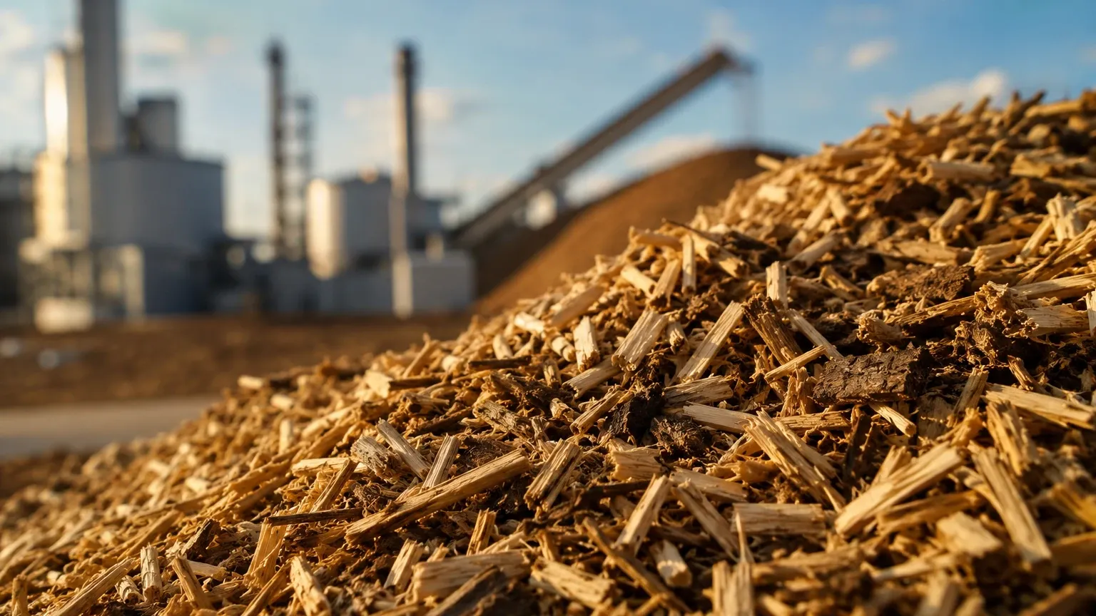
Proper installation is as critical as technology selection. Biomass materials do not settle like liquids; they form "cones" during filling and "craters" during discharge.
Angle of Repose
The angle of repose is the steepest angle at which a material remains stable. For wood chips, this can be between 30° and 45°. A biomass sensor must be positioned so that it does not point directly at the slope in a way that deflects the signal away from the receiver. Often, a swiveling mounting flange is used to aim the sensor at the most representative point of the material surface.
Dust Management
In wood pellet silos, dust is a constant factor. While radar can see through dust, the dust can eventually build up on the sensor face (the lens). Choosing a sensor with a PTFE or PFA lens cover helps prevent adhesion. Some sensors also include an air purge connection to blow compressed air across the lens, keeping it clear of debris.
Mounting Position
Sensors should never be mounted directly above the filling inlet. The falling stream of biomass will interfere with the signal and may damage the sensor over time. The ideal position is typically 1/3 of the diameter from the silo wall to get an average level reading.
Limitations and Common Risks
Despite advancements, there are inherent risks in biomass sensing that must be mitigated:
1. Bridging and Rat-holing: Biomass, particularly damp wood chips, can "bridge" across a silo, leaving an empty space beneath it. A top-mounted sensor will report that the silo is full, even if the discharge outlet is empty. In these cases, multiple sensors or point-level switches at the bottom are recommended.
2. Signal Attenuation: In very tall silos (over 30 meters / 98 feet), the signal return from low-dielectric biomass can be very weak. Using a high-gain antenna or a larger horn size for the radar sensor is necessary to ensure a reliable signal-to-noise ratio.
3. Combustible Dust Hazards: Biomass dust can be explosive (ATEX/IECEx zones). All sensors installed in these environments must carry the appropriate explosion-proof or intrinsically safe certifications.
Maintenance and Calibration
Biomass sensors are generally low-maintenance, but they are not "set and forget" devices.
* Seasonal Calibration: For capacitance or ultrasonic sensors, changes in humidity and temperature between winter and summer can necessitate recalibration.
* Visual Inspection: Periodically check for material build-up on the sensor face or probe, especially if the biomass has high resin or moisture content.
* Verification: Use a manual sounding tape occasionally to verify the electronic readings, especially during the first few months of operation.
Frequently Asked Questions (FAQ)
Q: Can I use a single biomass sensor for a very large rectangular bunker?
A: For large rectangular bunkers, a single sensor may only measure the level at one point. To get an accurate volume calculation, it is often better to use multiple sensors across the span or a specialized 3D solids scanner that maps the entire surface.
Q: How does moisture content affect radar sensors?
A: Increased moisture typically increases the dielectric constant of the biomass, which actually makes it easier for the radar to detect the surface. However, if the moisture leads to heavy condensation on the sensor lens, it may require an air purge system.
Q: Is ultrasonic technology suitable for sawdust?
A: Sawdust creates significant dust clouds during filling. These clouds can absorb ultrasonic sound waves, causing the sensor to "lose" the signal. 80 GHz radar is a much more reliable choice for sawdust applications.
Q: What is the maximum range for a biomass radar sensor?
A: Most industrial radar sensors for solids can measure up to 70 meters (approx. 230 feet), though the effective range depends on the reflectivity of the material and the antenna configuration.
Summary
Effective biomass management relies on selecting a sensor that can withstand dust, irregular surfaces, and low-reflectivity materials. While ultrasonic and point-level sensors have their place in simpler applications, 80 GHz non-contact radar has become the industry standard for continuous, high-accuracy biomass level measurement. By considering the angle of repose, dust accumulation, and safety certifications, plant operators can ensure a reliable fuel supply and efficient storage operations. For further technical specifications and to explore various measurement technologies, visit the Main Page for professional industrial solutions.