Boiler Water Level Control
Boiler Water Level Control
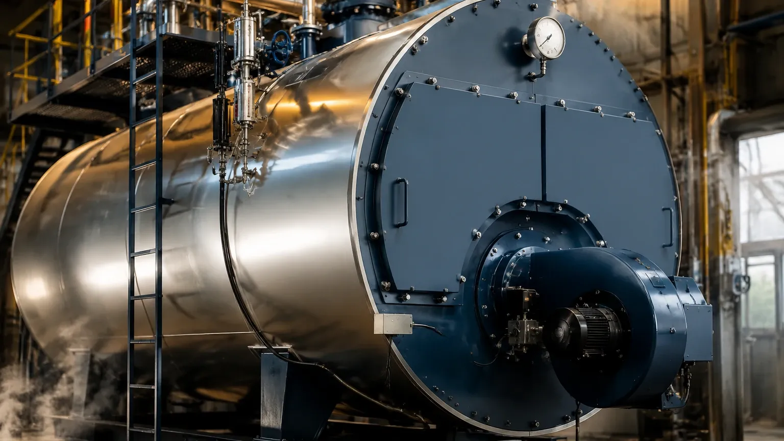
In industrial steam generation, boiler water level control is a critical safety and efficiency parameter. Maintaining the precise interface between the liquid water and the steam space ensures that the boiler tubes remain submerged to prevent overheating while simultaneously preventing water carryover into the steam header, which can damage downstream turbines and equipment. For process engineers and plant managers, selecting the appropriate instrumentation from a reliable manufacturer like Welk is the first step toward achieving stable and automated boiler operations.
Measurement Principles for Boiler Environments
Before implementing a control strategy, it is essential to understand the physics behind the measurement technologies used in high-temperature and high-pressure boiler environments. Each principle has specific advantages depending on the boiler type and operating conditions.
1. Buoyancy Principle (Magnetic Level Gauges)
This principle relies on Archimedes' Law. A float containing a permanent magnet is placed inside a bypass chamber connected to the boiler. As the water level rises or falls, the float moves accordingly. This movement is coupled with an external indicator or a reed-chain transmitter. Because the measurement is isolated from the process fluid by a non-magnetic chamber wall, it is highly robust against the high pressures typical of steam systems.
2. Time-of-Flight (Guided Wave Radar)
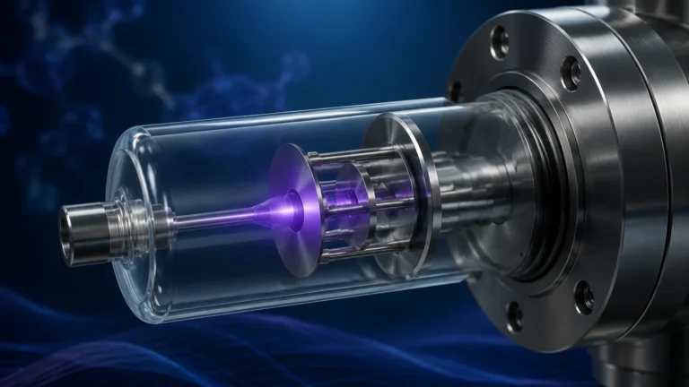
Guided Wave Radar (GWR) sends low-energy microwave pulses along a probe. When these pulses hit the water surface, a portion of the energy is reflected back to the transmitter. The time taken for the pulse to travel down and back is used to calculate the distance. In boiler water level control, GWR is often preferred over non-contact radar because the probe guides the signal, minimizing the impact of steam density and internal boiler obstructions.
3. Hydrostatic Pressure (Differential Pressure)
This method measures the pressure exerted by the column of water in the boiler. By comparing the pressure at the bottom of the vessel to the pressure in the steam space (using a differential pressure transmitter), the liquid level can be inferred. It is a standard method but requires careful compensation for changes in water density as temperatures fluctuate.
4. Conductivity and Capacitance
Conductivity probes detect the presence or absence of water at specific points, making them ideal for high and low-level alarms. Capacitance sensors measure the change in electrical capacitance between a probe and the vessel wall as the water level changes, providing a continuous measurement signal.
Boiler Water Level Control Strategies
The complexity of the control system depends on the boiler's capacity and the volatility of the steam demand. There are three primary configurations used in modern industrial plants.
Single-Element Control
This is the simplest form of control, where the feedwater valve is adjusted based solely on the water level measurement. While effective for small boilers with steady loads, it is susceptible to the "swell and shrink" effect. When steam demand suddenly increases, the pressure drop causes steam bubbles below the water surface to expand, making the level appear to rise (swell) even though the mass of water has decreased. A single-element system might incorrectly reduce feedwater flow during a swell.
Two-Element Control
To counteract the swell and shrink effect, two-element control incorporates a steam flow meter. The system calculates the required feedwater based on the amount of steam leaving the boiler, using the level measurement only as a corrective signal. This allows the system to anticipate the need for more water before the level actually drops.
Three-Element Control
For large-scale industrial boilers, three-element control is the gold standard. It measures the water level, the steam flow, and the feedwater flow. By comparing steam flow to feedwater flow, the controller can maintain a precise mass balance. This ensures that the Main Page of the control interface shows a stable level even during rapid load changes, protecting the boiler from thermal stress.
Practical Selection Table for Level Instrumentation
When choosing a Welk instrument for boiler applications, engineers should refer to the following technical comparison to ensure the device meets the process requirements.
| Technology | Max Temperature | Max Pressure | Accuracy | Best Application Case |
| :— | :— | :— | :— | :— |
| Magnetic Level Gauge | Up to 450°C | Up to 42 MPa | ±5 mm | Visual verification and redundant control |
| Guided Wave Radar | Up to 450°C | Up to 40 MPa | ±3 mm | High-precision continuous measurement |
| Hydrostatic Transmitter | Up to 120°C (Direct) | Variable | ±0.075% FS | Constant pressure, low-temperature tanks |
| Ultrasonic Sensor | Up to 80°C | 0.3 MPa | ±0.25% FS | Feedwater storage tanks (non-pressurized) |
| Level Switch | Up to 250°C | Up to 6.4 MPa | N/A (Point) | Emergency high/low-level cut-off |
Installation Considerations and Best Practices
Proper installation is as critical as device selection for reliable boiler water level control. High-temperature environments pose unique challenges for electronic components and mechanical seals.
1. Bypass Chambers and Still-wells: For radar and magnetic gauges, using a bypass chamber (side-mounted) isolates the sensor from the turbulence inside the main boiler drum. This results in a cleaner signal and allows for maintenance without shutting down the entire boiler.
2. Heat Dissipation: Transmitters and electronics should be mounted with cooling fins or extension necks if the process temperature exceeds the rated limit for the sensor head. This is particularly important for Guided Wave Radar units used on high-pressure steam drums.
3. Density Compensation: If using differential pressure (hydrostatic) measurement, the control system must be programmed with a density correction algorithm. As water heats from 20°C to 250°C, its density drops significantly, which can lead to measurement errors of 10% or more if not corrected.
4. Redundancy: Most safety codes (such as ASME) require at least two independent level sensing technologies for high-pressure boilers. A common configuration is a magnetic level gauge for visual and remote transmission paired with a guided wave radar or a series of conductivity switches for safety interlocking.
Common Risks and Limitations
Even with high-quality Welk instrumentation, certain process conditions can interfere with accurate level detection.
* Steam Dielectric Changes: In very high-pressure applications (above 10 MPa), the dielectric constant of steam increases, which can slow down the radar pulse. Modern GWR transmitters often include a "gas phase compensation" feature to automatically correct for this.
* Foaming: Chemical imbalances in the boiler water can lead to foaming. Foam is difficult for both radar and ultrasonic sensors to detect accurately, as it may absorb the signal or create a false surface. Maintaining proper water chemistry and blowdown schedules is essential.
* Scaling and Buildup: In boilers with high mineral content, scale can build up on probes or inside bypass chambers. Magnetic floats may become stuck, or radar signals may be attenuated. Regular inspection and the use of coated probes can mitigate these risks.
Frequently Asked Questions (FAQ)
Q: Why can't I use a standard ultrasonic sensor for boiler drum level?
A: Ultrasonic sensors rely on sound waves, which require a consistent medium. The high-pressure steam and temperature gradients in a boiler change the speed of sound unpredictably. Additionally, most ultrasonic transducers cannot withstand the high temperatures of a steam drum. They are better suited for ambient-temperature feedwater tanks.
Q: How often should magnetic level gauges be maintained?
A: In standard industrial applications, a semi-annual inspection is recommended. This involves flushing the bypass chamber to remove sediment and checking the float for any signs of damage or magnetic degradation.
Q: What is the benefit of a guided wave radar over a traditional DP transmitter?
A: GWR is generally less affected by changes in fluid density than differential pressure (DP) transmitters. While DP transmitters require complex compensation for temperature and pressure, GWR measures the surface directly, providing a more reliable reading during startup and shutdown phases when temperatures are changing rapidly.
Q: Can Welk instruments be used for SIL-rated safety loops?
A: Yes, many Welk level switches and transmitters are designed to meet Safety Integrity Level (SIL) requirements. When ordering, specify the required SIL rating to ensure the hardware and documentation meet the necessary functional safety standards.
Conclusion
Effective boiler water level control is a multi-faceted challenge that requires a deep understanding of both measurement physics and control logic. By selecting the right combination of magnetic gauges, radar sensors, and pressure transmitters, and by implementing robust two- or three-element control strategies, industrial facilities can ensure safe, continuous, and efficient steam production. For detailed technical specifications and support in selecting the right instrumentation for your specific boiler configuration, please visit our Main Page to review our full range of industrial level measurement solutions.