Calibrating Pressure Transmitter
Calibrating Pressure Transmitter
In industrial process control, the accuracy of data determines the efficiency and safety of the entire operation. Pressure transmitters are foundational instruments used to measure the pressure of gases, liquids, or steam. However, because these devices are often used to infer other variables—such as the level of a liquid in a tank or the flow rate through a pipe—their precision is paramount. Calibrating pressure transmitter units is a critical maintenance task that ensures the output signal (typically 4-20mA) accurately represents the physical pressure applied to the sensor.
This guide explores the technical principles behind pressure measurement, the step-by-step requirements for effective calibration, and the practical considerations engineers must address to maintain instrument integrity over time.
Understanding Pressure Transmitter Principles
Before discussing the specifics of calibrating pressure transmitter hardware, it is essential to understand how these devices function. Most modern industrial transmitters, such as those manufactured by Welk, utilize a sensing element that deforms under pressure. This physical deformation is converted into an electrical signal through various technologies.
Piezoresistive Sensors
These sensors consist of a diaphragm with strain gauges etched into it. When pressure is applied, the diaphragm flexes, changing the electrical resistance of the gauges. This change is proportional to the pressure and is processed by the transmitter's electronics.
Capacitive Sensors
In a capacitive pressure sensor, a sensing diaphragm is moved between two fixed plates. The change in capacitance between the diaphragm and the plates is measured to determine the applied pressure. These are known for high accuracy and stability in low-pressure applications.
Hydrostatic Level Measurement
In many liquid level applications, a pressure transmitter is used as a hydrostatic level sensor. The principle relies on the relationship between the height of a liquid column and the pressure at the base: $P = \rho \cdot g \cdot h$ (where $P$ is pressure, $\rho$ is density, $g$ is gravity, and $h$ is height). For these applications, calibrating pressure transmitter units involves ensuring the pressure reading correctly translates to the specific gravity of the fluid and the height of the vessel. For more information on specialized instruments for these tasks, you can Review product options and application support on the main site.
Why Calibrating Pressure Transmitter Units is Necessary
No instrument is immune to the effects of time and environment. Several factors necessitate a regular calibration schedule:
1. Drift: Over time, the electronic and mechanical components of a transmitter may shift, causing the "zero" or "span" to move away from the factory settings.
2. Environmental Stress: Extreme temperatures, vibration, and humidity can affect the sensitivity of the internal diaphragm and the stability of the circuit board.
3. Process Changes: If the density of the fluid being measured changes, or if the vessel is modified, the transmitter must be recalibrated to reflect the new process parameters.
4. Regulatory Compliance: Many industries, such as pharmaceuticals and food processing, require documented proof that instruments are operating within specified tolerances to meet safety and quality standards.
Essential Equipment for Calibration
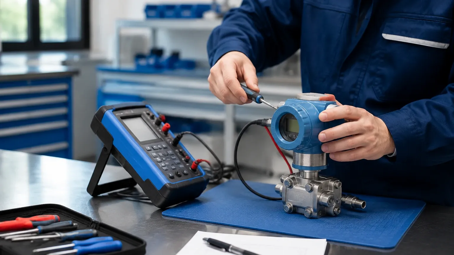
To perform a professional calibration, a technician requires a set of specialized tools to simulate process conditions and measure the resulting output accurately.
* Pressure Source: A hand pump (pneumatic or hydraulic) or a deadweight tester is used to apply a known, stable pressure to the transmitter.
* Reference Standard: A high-precision digital pressure gauge or calibrator that is significantly more accurate than the transmitter being tested (typically a 4:1 accuracy ratio).
* Multimeter/mA Calibrator: To measure the 4-20mA output signal from the transmitter.
* Power Supply: A 24V DC power source is usually required to power the transmitter during bench calibration.
* HART Communicator: For smart transmitters, a HART (Highway Addressable Remote Transducer) communicator is used to adjust digital parameters, perform electronic zeroing, and check diagnostics.
The Calibration Procedure: The 5-Point Check
The industry standard for calibrating pressure transmitter units is the 5-point check. This involves testing the transmitter at five specific intervals across its calibrated range: 0%, 25%, 50%, 75%, and 100% of the span.
Step 1: Preparation and Safety
If the transmitter is in the field, it must be isolated from the process using a manifold or block-and-bleed valves. Ensure the pressure is vented safely before disconnecting any lines.
Step 2: Zero Adjustment (LRV)
With zero pressure applied to the transmitter (vented to atmosphere for gauge pressure), the output should be exactly 4.000 mA. If the reading is outside the tolerance (e.g., 4.05 mA), the "Zero" adjustment is made. In smart transmitters, this is done via the HART communicator's "Sensor Trim" or "Zero Trim" function.
Step 3: Span Adjustment (URV)
Apply the maximum pressure of the transmitter’s calibrated range (the Upper Range Value or URV). The output should be exactly 20.000 mA. If it is not, the "Span" adjustment is performed. It is important to note that adjusting the span can sometimes affect the zero, so the process may need to be repeated.
Step 4: Linearity and Hysteresis Check
After setting the zero and span, the technician checks the intermediate points (25%, 50%, 75%).
* Linearity: Does the output increase proportionally with the pressure?
* Hysteresis: By checking the points while increasing pressure and then while decreasing pressure, the technician can determine if the sensor returns to the same value from both directions.
Step 5: Documentation
All readings (As-Found and As-Left) must be recorded. If the error is within the manufacturer’s specified tolerance (e.g., ±0.1% of span), the calibration is successful.
Selection and Technology Comparison Table
When choosing a transmitter for an application, understanding the calibration requirements and performance characteristics is vital. The following table compares common level and pressure measurement technologies used in industrial automation.
| Technology | Accuracy | Calibration Complexity | Ideal Application | Limitations |
| :— | :— | :— | :— | :— |
| Hydrostatic Pressure | High (0.1% – 0.25%) | Moderate | Water tanks, chemical storage | Sensitive to fluid density changes |
| Radar (Non-Contact) | Very High (±1-3mm) | Low (Initial Setup) | Corrosive liquids, solids | Higher initial cost |
| Ultrasonic | Moderate (±0.25%) | Low | Open channels, wastewater | Affected by foam, steam, and wind |
| Magnetic Level Gauge | Moderate | Low | High-pressure boilers | Mechanical parts can wear |
| Differential Pressure | High | High | Flow measurement, pressurized tanks | Requires impulse piping maintenance |
Installation Considerations for Accuracy
Even a perfectly calibrated transmitter will provide inaccurate data if installed incorrectly. When calibrating pressure transmitter systems, consider the following installation factors:
* Impulse Piping: For gas applications, the transmitter should be mounted above the process tap to allow condensate to drain back. For liquid applications, it should be mounted below the tap to ensure air bubbles can escape.
* Temperature Effects: Transmitters should be protected from direct heat sources. In high-temperature steam applications, a siphon or "pigtail" must be used to create a water seal that protects the sensor diaphragm from live steam.
* Mounting Position: Some high-precision sensors are sensitive to orientation. If a transmitter is calibrated in a vertical position but installed horizontally, the weight of the internal components may cause a slight zero shift.
* Manifold Usage: A 3-way or 5-way manifold is highly recommended. It allows for easy isolation and venting, making the process of calibrating pressure transmitter units in the field much safer and faster.
Common Risks and Limitations
While calibration corrects for drift, it cannot fix fundamental hardware issues. Technicians should be aware of these limitations:
1. Sensor Fatigue: If a diaphragm has been subjected to pressure spikes beyond its overpressure limit, it may become permanently deformed. Calibration cannot restore a damaged diaphragm.
2. Ambient Temperature Interference: Most transmitters have internal temperature compensation, but extreme swings can still cause "thermal drift." Calibration should ideally be performed at a temperature close to the operating environment.
3. Hysteresis and Repeatability: If a transmitter consistently provides different readings for the same pressure depending on whether the pressure is rising or falling, the sensor may be nearing the end of its service life.
4. Power Supply Fluctuations: Ensure the loop power is stable. A fluctuating power supply can induce noise in the 4-20mA signal, leading to false calibration errors.
Frequently Asked Questions (FAQ)
How often should I calibrate my pressure transmitter?
Most industrial standards suggest an annual calibration. However, for critical safety loops or high-accuracy custody transfer applications, a 6-month or even 3-month interval may be required. If the device shows high stability over several cycles, the interval can be extended.
What is the difference between "Re-ranging" and "Calibration"?
Re-ranging involves changing the LRV and URV (e.g., changing a 0-10 Bar range to 0-5 Bar) via software. Calibration involves applying a physical pressure to ensure the sensor's output matches the reference standard. Re-ranging does not verify the accuracy of the sensor.
Can I calibrate a transmitter without a pressure pump?
Only the "Zero" can be checked without a pump (by venting to atmosphere). To verify the span and linearity, a known pressure source must be applied to the sensor.
Does the density of the liquid matter for hydrostatic transmitters?
Yes. If a transmitter is calibrated for water (SG = 1.0) but used in oil (SG = 0.8), the level reading will be incorrect. The transmitter must be calibrated or scaled to account for the specific gravity of the process fluid.
Conclusion
Calibrating pressure transmitter units is a technical discipline that bridges the gap between raw physical force and actionable industrial data. By following a structured 5-point calibration procedure, using high-precision reference standards, and accounting for environmental and installation variables, engineers can ensure their process control systems remain accurate and reliable.
For organizations looking to upgrade their measurement infrastructure or source high-stability level and pressure instruments, selecting a manufacturer with a focus on precision and OEM/ODM flexibility is essential. To explore a comprehensive range of industrial level measurement solutions, including radar, ultrasonic, and hydrostatic transmitters, visit the Main Page for detailed technical specifications and application support.