Calibration in Instrumentation
Calibration in Instrumentation
In the realm of industrial automation and process control, the accuracy of data is the foundation of operational safety and efficiency. Calibration in instrumentation is the critical process of verifying and adjusting the performance of a measuring device to ensure its output accurately reflects the physical quantity being measured. For level measurement—a core component in water treatment, chemical processing, and oil and gas industries—calibration ensures that sensors correctly identify the volume, height, or mass of substances within a vessel.
Without rigorous calibration, even the most advanced radar or ultrasonic sensors can provide misleading data, leading to tank overflows, dry-running pumps, or compromised product quality. This article serves as a technical guide to the principles, methodologies, and practical considerations of calibration within the context of industrial level measurement instruments.
The Fundamental Principles of Calibration in Instrumentation
Calibration is fundamentally a comparison between a device under test (DUT) and a reference standard with known higher accuracy. In level instrumentation, this process typically involves defining the relationship between the physical level of a medium and the instrument's output signal, such as a 4-20 mA analog loop, a 0-10V signal, or a digital protocol like HART or Modbus.
Measurement Principles and Their Calibration Requirements
Different level measurement technologies rely on distinct physical principles, each requiring a specific approach to calibration:
1. Radar Level Meters (ToF): These utilize Time-of-Flight (ToF) technology, emitting microwave pulses that reflect off the material surface. Calibration involves setting the "Zero" point (usually the tank bottom) and the "Span" (the maximum fill level). Crucially, radar calibration must account for the dielectric constant of the medium and the tank's internal geometry to filter out false reflections from agitators or ladders.
2. Ultrasonic Sensors: Similar to radar but using sound waves, these sensors are highly dependent on the speed of sound. Calibration in instrumentation for ultrasonic devices must include temperature compensation, as the speed of sound varies with air temperature. The "dead zone" or blocking distance—typically 0.2 meters to 0.5 meters depending on the model—must also be factored into the calibration parameters.
3. Hydrostatic Pressure Transmitters: These measure the pressure exerted by a liquid column. The principle is based on the formula: $P = \rho \cdot g \cdot h$ (Pressure = Density × Gravity × Height). Calibration requires precise knowledge of the fluid's density. If the density changes due to temperature fluctuations, the instrument must be recalibrated or compensated to maintain accuracy.
4. Magnetic Level Gauges: These are mechanical-visual systems often paired with reed switches or transmitters. Calibration involves the physical alignment of the float's magnetic field with the external scale and the adjustment of transmitter zero/span points based on the float's position at minimum and maximum buoyancy.
Calibration Methodologies: Factory vs. Field
Calibration in instrumentation occurs at different stages of an instrument's lifecycle. Understanding the distinction between factory and field calibration is essential for maintenance planning.
Factory Calibration
Manufacturers like Welk perform factory calibration in controlled environments using high-precision reference standards, such as laser-calibrated liquid columns or automated pressure benches. This process establishes the instrument's baseline accuracy and linearity across its entire rated range. A calibration certificate is usually provided, documenting the traceability to national standards (e.g., NIST or ISO/IEC 17025).
Field Calibration (Commissioning)
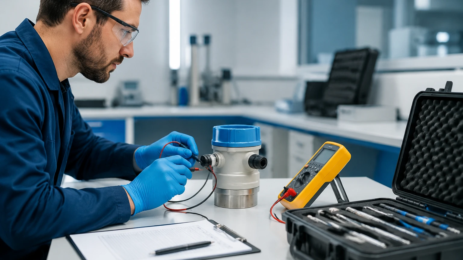
Field calibration is performed once the instrument is installed in its final operating environment. This is necessary because site-specific factors—such as mounting nozzle height, vessel internal obstructions, and specific gravity of the actual process fluid—can differ from factory test conditions. Field calibration often involves "Wet Calibration" (using actual liquid) or "Dry Calibration" (using electronic simulation or mathematical calculation based on tank dimensions).
Technical Evaluation Criteria for Calibration
When evaluating the calibration of an instrument, engineers must look beyond simple accuracy. The following criteria define the quality of the calibration:
* Accuracy: The degree of conformity of the measured value to the actual value. For high-end radar meters, this may be as precise as ±2 mm.
* Repeatability: The ability of the instrument to provide the same output for the same input under identical conditions over a short period.
* Hysteresis: The difference in output when the same level is approached from an increasing direction versus a decreasing direction. High hysteresis often indicates mechanical wear or friction in float-based systems.
* Linearity: The maximum deviation of the instrument's output curve from a straight line. Level instruments should ideally exhibit high linearity across the 0% to 100% range.
* Traceability: The documented pedigree of the calibration, showing an unbroken chain of comparisons back to a recognized national or international standard.
Selection Table: Calibration Requirements by Technology
| Technology | Typical Accuracy | Calibration Complexity | Primary Calibration Variable |
| :— | :— | :— | :— |
| Radar (80GHz) | ±1 mm to ±3 mm | Moderate | Tank Geometry / Dielectric Constant |
| Ultrasonic | ±0.25% of Range | Low | Temperature / Speed of Sound |
| Hydrostatic | ±0.1% to ±0.5% | Low to Moderate | Fluid Density / Specific Gravity |
| Magnetic Gauge | ±5 mm to ±10 mm | Low | Float Buoyancy / Magnet Alignment |
| Level Switch | N/A (Point) | Very Low | Sensitivity / Switching Point |
Installation Considerations and Their Impact on Calibration
Calibration in instrumentation is only as effective as the installation allows. Improper mounting can introduce errors that calibration cannot fully rectify.
1. Nozzle Geometry: For radar and ultrasonic sensors, the mounting nozzle should be short and smooth. A nozzle that is too long can create internal reflections (ringing) that interfere with the "Zero" calibration point.
2. Stilling Wells: In applications with heavy turbulence or foam, stilling wells (pipes) are used to provide a calm surface. Calibration must then be adjusted to account for the restricted environment within the pipe, particularly for radar sensors where the pipe diameter affects wave propagation.
3. Hydrostatic Offsets: When installing a pressure transmitter at the bottom of a tank, the sensor might be located a few centimeters below the actual "zero" level of the tank. This physical offset must be programmed into the transmitter as a "Zero Offset" to ensure the displayed level starts at 0.00 meters when the tank is empty.
Common Risks and Troubleshooting in Calibration
Failure to maintain a proper calibration schedule or using incorrect procedures can lead to significant operational risks.
* Sensor Drift: Over time, electronic components age and mechanical parts wear, causing the instrument's output to "drift" away from the calibrated values. Regular verification intervals (e.g., annually) are recommended.
* Environmental Influence: Significant changes in ambient temperature or process pressure can affect the calibration of ultrasonic and hydrostatic sensors. If an instrument lacks automatic compensation, manual recalibration during seasonal changes may be necessary.
* Build-up and Scaling: In chemical or wastewater applications, material build-up on the sensor face (for ultrasonic/radar) or the diaphragm (for hydrostatic) can simulate a level change. Calibration should be checked after cleaning to ensure the "Zero" point remains valid.
Frequently Asked Questions (FAQs)
Q: How often should level instruments be calibrated?
A: The frequency depends on the criticality of the application and the stability of the technology. For safety-instrumented systems (SIS), semi-annual calibration may be required. For general monitoring, an annual check is standard. Radar and magnetic gauges generally require less frequent calibration than hydrostatic or ultrasonic sensors.
Q: Can I calibrate a radar level meter in an empty tank?
A: Yes, most modern radar meters allow for "Dry Calibration." By inputting the precise distance from the sensor face to the tank bottom and the desired span, the instrument can calculate the level. However, a "Wet" verification at one or two points is always recommended to confirm accuracy.
Q: What is the difference between calibration and adjustment?
A: Calibration is the act of *checking* the instrument against a standard and documenting the error. Adjustment is the act of *modifying* the instrument's output to minimize that error. In common industrial parlance, "calibration" often refers to the entire process of checking and adjusting.
Conclusion
Calibration in instrumentation is not merely a maintenance task; it is a fundamental requirement for process integrity. Whether utilizing the precision of high-frequency radar or the reliability of hydrostatic pressure transmitters, understanding the underlying measurement principles is the first step toward effective calibration. By following rigorous standards and considering the specific environmental factors of each application, engineers can ensure that their level measurement systems provide the accurate data necessary for modern industrial operations.
For those seeking professional-grade hardware designed for ease of calibration and long-term stability, it is advisable to Review product options and application support on our Main Page to find the right solution for your specific industry requirements. Proper instrument selection, combined with a robust calibration strategy, ensures the longevity and safety of your industrial assets.