Calorimetric Measuring Principle
Calorimetric Measuring Principle
In the field of industrial process automation, the calorimetric measuring principle—often referred to as the thermal dispersion or thermal mass principle—stands as a highly reliable method for monitoring the flow and level of fluids. Unlike mechanical measurement systems that rely on moving parts such as paddles or turbines, calorimetric sensors utilize the physical properties of heat transfer to determine the state of a medium. This principle is widely adopted in industries ranging from water treatment and chemical processing to oil and gas, primarily due to its robustness, minimal maintenance requirements, and high sensitivity to low flow velocities.
For engineers and system integrators, understanding the underlying physics and practical application of the calorimetric measuring principle is essential for selecting the right instrumentation. This guide provides a technical deep dive into how these sensors function, their industrial applications, and the critical factors to consider during selection and installation. For a broader look at industrial measurement solutions, technical professionals can refer to the Main Page for comprehensive product specifications.
1. Understanding the Calorimetric Measuring Principle
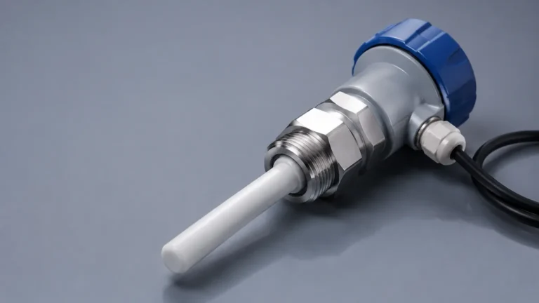
The calorimetric measuring principle is based on the laws of thermodynamics, specifically the correlation between the flow of a fluid and the dissipation of heat. In a typical sensor configuration, two temperature sensors (usually Resistance Temperature Detectors or RTDs, such as Pt100 or Pt1000) are placed in direct contact with the medium.
The Physics of Heat Dissipation
One of these sensors is designated as the "reference sensor," which measures the ambient temperature of the medium. The second sensor is the "active sensor," which is heated to a specific temperature above that of the medium by an internal heating element. When the medium is stationary (zero flow) or when a level switch is not submerged, a specific temperature differential ($ΔT$) exists between the two sensors.
As the medium begins to move (in flow applications) or when the sensor becomes submerged in a liquid (in level applications), the medium absorbs heat from the active sensor and carries it away. This cooling effect reduces the temperature of the active sensor. The rate at which this heat is dissipated is directly proportional to the mass flow rate of the medium or the thermal conductivity of the fluid surrounding the probe.
Measurement Modes
There are two primary electronic methods used to process this signal:
1. Constant Power Mode: A constant amount of heating power is supplied to the active sensor. The electronics measure the resulting temperature difference between the heated and reference sensors. A higher flow rate or higher thermal conductivity results in a smaller temperature difference.
2. Constant Temperature Difference Mode: The electronics adjust the heating power to maintain a constant temperature difference between the two sensors. In this scenario, the amount of power required to maintain the $ΔT$ is the measurement variable. This method is often preferred for its faster response times and wider measuring ranges.
2. Technical Components and Signal Processing
To ensure accuracy in demanding industrial environments, the construction of a calorimetric sensor must be precise. The probe tip is typically manufactured from high-grade stainless steel (316L) or specialized alloys like Hastelloy for corrosive environments.
Sensor Construction
The RTDs are embedded within the metal probe, often encapsulated in a thermally conductive ceramic or epoxy to ensure efficient heat transfer while maintaining electrical isolation. The design must minimize "thermal lagging," where the mass of the probe itself delays the detection of temperature changes in the fluid.
Signal Evaluation
The raw signal from the RTDs is processed by an integrated or remote transmitter. In point level detection, the transmitter compares the heat dissipation rate against a pre-defined threshold. When the probe is immersed in a liquid, the heat dissipation is significantly higher than when it is in air or gas, allowing the device to trigger a switch output. In flow monitoring, the transmitter converts the cooling rate into a flow velocity (m/s) or a volumetric flow rate, often providing both analog (4-20 mA) and digital (IO-Link, Modbus) outputs.
3. Applications in Industrial Level and Flow Monitoring
While the calorimetric measuring principle is a staple for flow switches, its application in level measurement is equally vital, particularly for point level detection in challenging conditions.
Point Level Detection
In level measurement, calorimetric sensors act as highly sensitive switches. They are frequently used for:
* Dry-Run Protection: Protecting pumps by ensuring they do not operate without fluid. The sensor detects the loss of liquid and shuts down the pump within seconds.
* Leak Detection: Monitoring for the presence of liquid in secondary containment areas or double-walled tanks.
* Overfill Prevention: Acting as a high-level alarm in tanks where foaming or turbulence might interfere with ultrasonic or radar sensors.
Flow Monitoring
As flow monitors, these devices are prized for their ability to detect very low flow rates that would not move a mechanical paddle. Common uses include:
* Cooling Circuit Monitoring: Ensuring that coolant is flowing through heat exchangers or welding robots.
* Lubrication Systems: Verifying the flow of oil to bearings in heavy machinery.
* Filter Monitoring: Detecting changes in flow that indicate a clogged filter element.
4. Selection Criteria and Engineering Considerations
Selecting a sensor based on the calorimetric measuring principle requires an evaluation of the medium's properties and the process conditions. Because the measurement relies on thermal conductivity, variations in the medium can affect the calibration.
Media Properties
Different fluids have different thermal conductivities. For example, water dissipates heat much more efficiently than oil. If a sensor is calibrated for water but used in an oil-based hydraulic system, the setpoints must be adjusted. Furthermore, the presence of solids or air bubbles can cause signal fluctuations.
Selection Table: Calorimetric vs. Alternative Technologies
| Feature | Calorimetric Switch | Tuning Fork (Vibrating) | Ultrasonic Level | Magnetic Flow Meter |
| :— | :— | :— | :— | :— |
| Moving Parts | None | None | None | None |
| Media Type | Liquids & Gases | Liquids & Solids | Liquids & Solids | Conductive Liquids |
| Pressure Range | Up to 100 bar (1450 psi) | Up to 64 bar (928 psi) | Atmospheric | Up to 40 bar (580 psi) |
| Sensitivity | Very High (Low flow) | Medium | High | High |
| Viscosity Limit | Moderate | High | High | Low to Medium |
| Maintenance | Low | Low | Low | Low |
Operating Parameters
* Temperature Range: Standard sensors typically operate between -20°C and +80°C (-4°F to 176°F), though high-temperature versions can reach 150°C (302°F).
* Pressure Resistance: Solid-state construction allows these sensors to withstand high process pressures, often exceeding 100 bar (1450 psi).
* Response Time: For level detection, response times are usually under 2 seconds. For flow, the response depends on the change in velocity but is generally between 1 and 10 seconds.
5. Installation Best Practices
Proper installation is paramount to the accuracy of any thermal-based measurement. Incorrect placement can lead to false readings or premature sensor failure.
Orientation and Positioning
For flow monitoring, the sensor probe must be fully immersed in the flow stream. It is recommended to install the sensor in a vertical pipe with an upward flow direction to ensure the pipe is always full and to prevent air pockets from gathering around the sensor tip.
In horizontal pipes, the sensor should be installed from the side. Mounting from the top may lead to errors if air bubbles accumulate, while mounting from the bottom may lead to errors if sediment or sludge settles on the sensor tip.
Straight Pipe Runs
To achieve a stable flow profile, calorimetric flow monitors require straight pipe runs before and after the installation point. A general rule of thumb is to have at least 5 to 10 times the pipe diameter (D) of straight pipe upstream and 3 to 5 times the diameter downstream. If elbows, valves, or pumps are located near the sensor, these distances should be increased to mitigate turbulence.
Immersion Depth
The active part of the probe (the tip) must be positioned where the velocity is representative of the total flow. In most industrial pipes, this is at approximately 1/7th to 1/8th of the pipe diameter, or simply at the center for smaller diameters.
6. Limitations and Maintenance
While the calorimetric measuring principle offers many advantages, engineers must be aware of its limitations to avoid application failures.
Coating and Fouling
Since the principle relies on heat transfer between the probe and the medium, any buildup on the sensor tip acts as an insulator. Scaling, paraffin wax, or heavy biological growth will slow down the response time and eventually cause the sensor to fail or provide inaccurate readings. In applications with "dirty" media, periodic cleaning of the probe tip is required.
Rapid Temperature Fluctuations
Because the sensor measures temperature differences, sudden and extreme changes in the process temperature (e.g., during a Clean-in-Place or CIP cycle) can cause temporary switching errors. Most modern calorimetric sensors include temperature compensation logic to minimize this effect, but it remains a factor in high-precision applications.
Viscosity and Conductivity
Extremely viscous fluids may not carry heat away from the sensor as efficiently as thinner liquids, leading to a non-linear response. Additionally, while the principle works in almost all liquids, the specific heat capacity of the fluid must be relatively constant for the calibration to remain valid.
7. Frequently Asked Questions (FAQs)
Q: Can calorimetric sensors be used in hazardous areas?
A: Yes, many manufacturers provide versions with ATEX, IECEx, or FM certifications for use in explosive gas or dust atmospheres. These typically use intrinsically safe (Ex i) or flameproof (Ex d) protection methods.
Q: How does the calorimetric principle compare to mechanical flow switches?
A: Calorimetric switches have no moving parts, meaning they do not suffer from mechanical wear, sticking, or paddle breakage. They also offer much lower pressure drop and can detect much lower flow velocities.
Q: Is calibration required for different liquids?
A: Yes. Because different liquids have different thermal properties (e.g., water vs. glycol), a sensor calibrated for water will trigger at a different point if used in glycol. Many high-end sensors allow for field-calibration or have pre-set curves for common industrial fluids.
Q: Can this principle measure gas flow?
A: Absolutely. The calorimetric measuring principle is one of the most common methods for thermal mass flow meters used in compressed air, nitrogen, and natural gas monitoring. However, the sensor design for gas is often different from that used for liquids due to the lower heat capacity of gases.
Conclusion
The calorimetric measuring principle provides a sophisticated yet durable solution for modern industrial fluid management. By eliminating moving parts and leveraging the reliable physics of thermal dispersion, these sensors offer long-term stability and high sensitivity. Whether used for protecting a critical pump from dry-running or ensuring the consistent flow of coolant in an automated assembly line, the calorimetric sensor is a versatile tool in the engineer's arsenal.
When selecting a device, it is crucial to match the sensor material, pressure rating, and electronic output to the specific demands of the application. For detailed guidance on selecting the appropriate level or flow instrumentation for your project, visit the Main Page to explore professional-grade measurement solutions tailored for industrial automation.