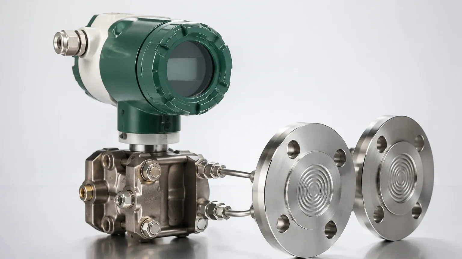
Dp Flow Transmitter
Dp Flow Transmitter
Differential pressure (DP) flow measurement remains one of the most widely utilized technologies in industrial process control. Despite the emergence of ultrasonic and Coriolis meters, the use of a dp flow transmitter in conjunction with a primary flow element offers a robust, well-understood, and cost-effective solution for measuring the flow of liquids, gases, and steam. This technology relies on established physical laws and is standardized globally, making it a reliable choice for engineers in water treatment, chemical processing, and oil and gas industries.
Measurement Principles
The operation of a dp flow transmitter is based on Bernoulli’s principle, which states that an increase in the velocity of a fluid occurs simultaneously with a decrease in static pressure. In a closed pipe, this is achieved by introducing a deliberate restriction—known as a primary element—into the flow path.
As the fluid passes through the restriction, its velocity increases, and its pressure drops. The difference between the pressure upstream of the restriction ($P_1$) and the pressure downstream ($P_2$) is the differential pressure ($ΔP$). According to the continuity equation and Bernoulli’s theorem, the flow rate is proportional to the square root of this differential pressure:
$$Q = k \cdot \sqrt{\Delta P}$$
Where:
- $Q$ is the volumetric or mass flow rate.
- $k$ is a flow coefficient determined by the geometry of the restriction, the pipe diameter, and the fluid properties (such as density and viscosity).
- $\Delta P$ is the differential pressure measured by the transmitter.
Because the relationship is non-linear, the dp flow transmitter or the receiving control system must perform a "square root extraction" to convert the pressure signal into a linear flow reading. Modern digital transmitters typically handle this calculation internally, providing a linear 4-20mA or digital output (HART, Foundation Fieldbus, or Profibus).
Primary Flow Elements
The accuracy and performance of a DP flow system depend heavily on the selection of the primary element. Each type has specific advantages regarding pressure loss, cost, and suitability for different fluid types.
1. Orifice Plates
An orifice plate is a thin metal plate with a precisely machined hole (typically concentric) placed between two flanges. It is the most common primary element due to its low cost and ease of installation. However, it creates a significant permanent pressure loss and is susceptible to wear over time, especially with abrasive fluids.
2. Venturi Tubes
A Venturi tube consists of a converging conical section, a cylindrical throat, and a diverging recovery section. It is designed to minimize permanent pressure loss and is ideal for high-velocity flows or applications where energy efficiency is critical. It is also more resistant to erosion than an orifice plate.
3. Flow Nozzles
Flow nozzles are essentially a hybrid between an orifice plate and a Venturi tube. They are particularly effective for high-velocity, high-temperature steam flows and are more durable than orifice plates in erosive environments.
4. Averaging Pitot Tubes (Annubars)
These elements measure the difference between the impact pressure (stagnation pressure) and the static pressure. They consist of a probe inserted across the pipe diameter. They offer very low pressure loss and are easy to install in existing large-diameter pipelines.
Selection Criteria and Comparison
When selecting a dp flow transmitter and primary element, engineers must balance initial costs against long-term operational performance. The following table provides a comparison of the most common primary elements used in industrial applications.
| Feature | Orifice Plate | Venturi Tube | Flow Nozzle | Averaging Pitot Tube |
| :— | :— | :— | :— | :— |
| Accuracy | Good (±0.5% to ±2%) | Excellent (±0.5% to ±1%) | Good (±1% to ±2%) | Fair (±1% to ±2%) |
| Pressure Loss | High | Low | Medium | Very Low |
| Initial Cost | Low | High | Medium | Medium |
| Installation | Easy (between flanges) | Difficult (long body) | Moderate | Easy (single insertion) |
| Suitability | Clean liquids/gases | Slurries/high velocity | Steam/high temp | Large pipes/gas |
For comprehensive technical specifications and to explore various measurement options, engineers can refer to the Main Page for detailed product catalogs and application support.
Installation Considerations
The accuracy of a dp flow transmitter is highly dependent on proper installation. Because the technology relies on stable pressure profiles, any turbulence in the fluid can lead to significant errors.
Straight Pipe Requirements
To ensure a fully developed flow profile, primary elements require a minimum length of straight pipe upstream and downstream. Typically, a minimum of 10 to 20 pipe diameters (D) upstream and 5D downstream is required. If these distances cannot be met due to space constraints, flow conditioners or rectifiers must be installed.
Impulse Line Piping
Impulse lines (or sensing lines) transport the pressure from the pipe to the transmitter. These lines must be carefully managed:
- Slope: Lines should be sloped at least 1:12 to allow gas bubbles to vent back into the pipe (in liquid service) or condensate to drain back (in gas service).
- Distance: Keep impulse lines as short as possible to minimize response lag and temperature-induced density changes.
- Manifolds: A 3-valve or 5-valve manifold is essential for commissioning and maintenance. It allows the transmitter to be isolated and the zero-point to be checked without shutting down the process.
Orientation for Different Media
- Liquid Flow: The transmitter should be mounted below the primary element so that any air bubbles can rise and escape back into the process line.
- Gas Flow: The transmitter should be mounted above the primary element so that any liquid condensate can drain back into the pipe.
- Steam Flow: The transmitter is typically mounted below the pipe, but with "condensate pots" to ensure the impulse lines are filled with water, protecting the transmitter sensor from high-temperature steam.
Limitations and Challenges
While versatile, the dp flow transmitter has specific limitations that must be addressed during the design phase:
1. Turndown Ratio: Standard DP systems typically have a limited turndown ratio (the ratio of maximum to minimum flow measurement) of about 3:1 or 4:1. This is because of the square root relationship; at low flow rates, the differential pressure becomes too small to measure accurately. Multi-variable transmitters can improve this range.
2. Permanent Pressure Loss: The energy required to overcome the restriction in the pipe represents a permanent loss in the system, which can increase pumping or compression costs over time.
3. Density Sensitivity: Since DP meters measure volume flow based on pressure, changes in fluid density (caused by temperature or pressure fluctuations) will affect accuracy. In gas and steam applications, pressure and temperature compensation is often required.
4. Clogging: Impulse lines are susceptible to clogging if the fluid contains solids or if the fluid can freeze or solidify at ambient temperatures.
Frequently Asked Questions (FAQs)
Q: Why is square root extraction necessary?
A: Because the differential pressure generated by a primary element increases with the square of the flow rate. To provide a linear representation of the flow (e.g., doubling the flow results in doubling the output signal), the square root of the $\Delta P$ must be calculated.
Q: Can a dp flow transmitter be used for level measurement?
A: Yes. Hydrostatic level measurement is a common application for DP transmitters. By measuring the pressure at the bottom of a tank and comparing it to the headspace pressure (in closed tanks), the transmitter can calculate the liquid level based on the fluid's density.
Q: What is the purpose of a 5-valve manifold?
A: A 5-valve manifold includes two block valves, one equalizer valve, and two vent/drain valves. This configuration allows for the safe isolation of the transmitter, equalization of pressure for zero-calibration, and the venting of trapped process fluid or gas before removal.
Q: How does the Beta ratio (β) affect measurement?
A: The Beta ratio is the ratio of the orifice diameter to the internal pipe diameter ($d/D$). A lower Beta ratio generates a higher differential pressure (better for low flows) but results in a higher permanent pressure loss. Most designs aim for a Beta ratio between 0.3 and 0.7.
Conclusion
The dp flow transmitter remains a cornerstone of industrial process instrumentation due to its adaptability and the vast amount of empirical data supporting its use. By understanding the relationship between the primary element and the transmitter, and by adhering to strict installation guidelines regarding impulse lines and straight pipe runs, operators can achieve high levels of accuracy and reliability. For those seeking to integrate these systems into complex automation environments, selecting high-quality instruments and following established engineering standards is the key to long-term success in flow and level management.