Capacitance Gas Level Measurement Sensor
Capacitance Gas Level Measurement Sensor
In industrial process control, the accurate monitoring of liquefied gases and high-pressure storage tanks is critical for safety and operational efficiency. A capacitance gas level measurement sensor represents a robust, solid-state solution for these demanding environments. Unlike mechanical floats or optical sensors, capacitance-based technology relies on the electrical properties of the stored medium, making it particularly effective for substances with consistent dielectric properties, such as liquefied petroleum gas (LPG), liquid nitrogen, and various refrigerants.
As a specialized instrument within the broader portfolio of industrial automation, these sensors provide continuous level monitoring without moving parts. This guide explores the engineering principles, selection criteria, and practical installation requirements for integrating capacitance technology into gas storage and processing systems.
Measurement Principle of Capacitance Sensors
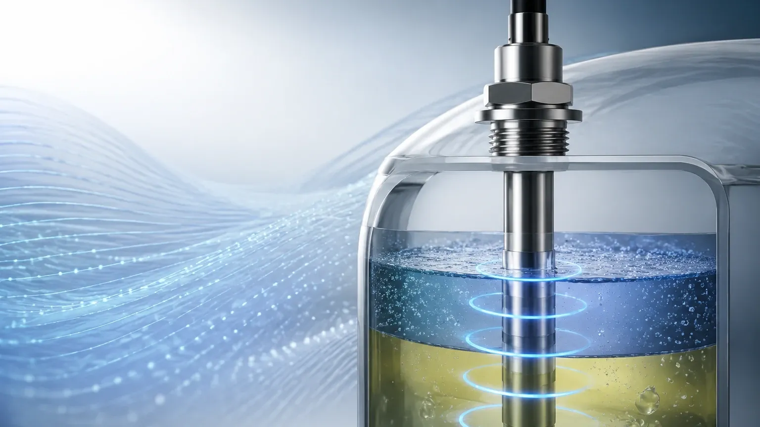
The operation of a capacitance gas level measurement sensor is based on the physical principle of a capacitor. In a typical industrial setup, the sensor probe acts as one electrode, while the vessel wall (if conductive) acts as the second electrode. If the tank is non-conductive, a reference rod or sleeve is used as the second electrode.
The space between these two electrodes is filled with the medium being measured. The capacitance ($C$) of this system is defined by the formula:
$$C = \epsilon \cdot \frac{A}{d}$$
Where:
* $\epsilon$ (Epsilon): The dielectric constant (permittivity) of the material between the electrodes.
* A: The surface area of the electrodes.
* d: The distance between the electrodes.
In a level measurement application, the distance ($d$) and the area ($A$) remain constant. The variable factor is the total dielectric constant of the medium between the probe and the wall. As the liquid level of the gas (in its liquefied state) rises, it displaces the gas phase (vapor) surrounding the probe. Since the liquid phase has a higher dielectric constant than the gas phase, the total capacitance increases proportionally with the level. The electronics within the sensor head convert this change in picofarads (pF) into a standard industrial signal, typically 4-20mA or a digital protocol like Modbus or HART.
Key Components and Construction
To ensure reliability in high-pressure gas applications, capacitance sensors are engineered with specific materials:
1. The Probe (Electrode): Usually made of stainless steel (316L). For corrosive gases or conductive liquids, the probe is fully insulated with materials like PTFE (Polytetrafluoroethylene) or PFA.
2. The Insulation: High-grade polymers ensure that the electrical charge does not short-circuit to the tank wall through the medium.
3. The Electronic Insert: This module performs the capacitance-to-current conversion. Modern units include temperature compensation to account for shifts in the dielectric constant caused by thermal fluctuations.
4. Process Connection: Threaded or flanged connections designed to withstand high pressures, often exceeding 40 bar (approx. 580 psi) in gas storage applications.
Selection Criteria for Gas Level Measurement
When selecting a capacitance gas level measurement sensor, engineers must evaluate the physical properties of the gas and the vessel geometry. The following table provides a selection framework based on common industrial parameters:
| Parameter | Requirement/Consideration | Impact on Sensor Selection |
| :— | :— | :— |
| Dielectric Constant ($\epsilon_r$) | Must be stable and significantly different from air ($\epsilon_r \approx 1$). | Low $\epsilon_r$ media (e.g., LPG $\epsilon_r \approx 1.6-1.9$) require high-sensitivity electronics. |
| Conductivity | Most liquefied gases are non-conductive. | Non-insulated probes can be used for non-conductive media, but insulated probes are safer for general use. |
| Tank Material | Metal vs. Plastic/Fiberglass. | Plastic tanks require a concentric shield or a double-pole probe to provide a reference ground. |
| Pressure Rating | Must exceed the maximum vapor pressure of the gas. | High-pressure seals (glass-to-metal) are required for hazardous gas storage. |
| Temperature Range | Cryogenic (LNG) to high-temperature processing. | Specialized stand-offs or cooling fins may be needed to protect the electronics. |
For comprehensive technical specifications and to explore various sensor configurations, engineers can refer to the Main Page of professional instrumentation providers like Welk.
Installation and Calibration Procedures
Proper installation is paramount for the accuracy of a capacitance gas level measurement sensor. Because the technology relies on the electrical field between the probe and the ground, the following steps must be followed:
Mechanical Mounting
* Avoid Obstructions: The probe should be installed at least 100mm away from the tank wall and any internal structures like ladders or agitators to prevent false capacitance readings.
* Vertical Alignment: The sensor must be mounted vertically. In horizontal cylindrical tanks, the probe length must be carefully calculated to cover the full diameter.
* Grounding: Ensure a low-resistance electrical connection between the sensor housing and the metal tank. If the tank is lined or made of non-conductive material, a reference ground rod is mandatory.
Calibration
Calibration typically involves a two-point adjustment:
1. Zero Adjustment (0%): Performed when the tank is empty or the level is at the bottom of the probe. This sets the baseline capacitance of the vapor phase.
2. Span Adjustment (100%): Performed when the tank is full or at the maximum desired measurement point. This captures the capacitance of the liquid phase.
Modern digital sensors often allow for "dry calibration," where the dielectric constant and tank dimensions are entered manually, though "wet calibration" remains the most accurate method for complex gas mixtures.
Advantages and Limitations
Advantages
* No Moving Parts: High reliability and low maintenance in pressurized systems.
* High Pressure/Temperature Resistance: Capable of operating in environments where ultrasonic or radar sensors might face signal attenuation or seal failure.
* Cost-Effective: Generally more affordable than guided wave radar for simple, non-conductive liquid gas applications.
* Fast Response: Provides real-time data suitable for rapid filling or discharge operations.
Limitations
* Dielectric Sensitivity: If the composition of the gas mixture changes significantly, the dielectric constant may shift, leading to measurement errors unless the sensor is recalibrated.
* Coating and Buildup: While less of an issue with clean gases, any conductive buildup on the probe can cause "bridging," resulting in a permanent high-level error signal.
* Vessel Geometry: Requires a consistent ground reference; changing the probe's proximity to the wall after calibration will invalidate the readings.
Comparison with Alternative Technologies
In the context of gas level measurement, capacitance is often weighed against Radar and Ultrasonic technologies.
* VS. Ultrasonic: Ultrasonic sensors rely on sound waves and are often unsuitable for pressurized gas environments because the speed of sound changes with gas density and pressure. Capacitance sensors are unaffected by these atmospheric changes.
* VS. Radar: Radar (specifically Guided Wave Radar) is highly accurate and less sensitive to dielectric changes. However, capacitance sensors are often preferred for their simplicity and lower cost in applications where the medium is consistent, such as pure CO2 or Ammonia storage.
Maintenance and Troubleshooting
While capacitance gas level measurement sensors are largely maintenance-free, periodic checks are recommended to ensure long-term accuracy:
1. Insulation Integrity: For insulated probes, check for cracks or wear in the PTFE/PFA coating, especially if the medium is corrosive.
2. Moisture in Housing: Ensure that cable glands are sealed. Moisture in the electronic housing can introduce stray capacitance, causing the signal to drift.
3. Signal Verification: Periodically compare the sensor output against a manual gauge or a secondary level switch to confirm calibration stability.
Common Troubleshooting Scenarios
* Reading stays at 100%: This often indicates a short circuit between the probe and the tank wall or significant conductive buildup.
* Erratic Signal: Check for loose grounding connections or electromagnetic interference (EMI) from nearby high-power equipment. Ensure the use of shielded cables.
* Non-linear Output: Usually caused by the probe being too close to internal tank structures or the tank wall not being parallel to the probe.
Frequently Asked Questions (FAQ)
Q: Can a capacitance sensor be used for liquefied natural gas (LNG)?
A: Yes, but it requires specialized cryogenic construction to handle temperatures near -162°C. The probe materials and seals must be rated for these extremes.
Q: How does pressure affect the capacitance reading?
A: In the liquid phase, pressure has a negligible effect on the dielectric constant. However, in the vapor phase, high pressure increases the density of the gas, which slightly increases its dielectric constant. High-precision applications may require compensation for this.
Q: Is it possible to cut a capacitance probe to length in the field?
A: Some models allow for field-cutting, but this requires recalibration and, in the case of insulated probes, specialized kits to reseal the end of the probe to prevent fluid ingress.
Q: What is the maximum length for a capacitance gas level probe?
A: Rigid rod probes are typically available up to 3 or 4 meters. For deeper tanks or silos, flexible cable probes can extend up to 20 or 30 meters, though they require a bottom weight to remain tensioned.
For those seeking reliable measurement solutions, Welk provides a range of industrial instruments designed for accuracy and durability. To view specific product data sheets and application notes, visit the Main Page.
By understanding the dielectric properties of the process medium and adhering to strict installation standards, engineers can leverage the capacitance gas level measurement sensor as a dependable component of their industrial control strategy.