Capacitance Level Switch
Capacitance Level Switch
In the landscape of industrial automation, point level detection serves as a critical safeguard for process continuity and safety. Among the various technologies available, the capacitance level switch remains a staple for engineers due to its lack of moving parts, robustness in harsh environments, and versatility across both liquid and solid media. This guide provides a comprehensive technical overview of capacitance level switches, detailing their operational physics, selection criteria, and practical application in modern industrial settings.
Understanding the Measurement Principle
The operation of a capacitance level switch is based on the electrical principle of a capacitor. In its simplest form, a capacitor consists of two conductive plates separated by an insulating material known as a dielectric. The ability of this setup to store an electrical charge is defined as capacitance ($C$).
In an industrial level sensing application, the sensor probe (electrode) acts as one plate of the capacitor, while the vessel wall (if conductive) acts as the second plate. If the vessel is non-conductive, a reference electrode or a ground probe is used. The space between the probe and the wall is occupied by the process material, which serves as the dielectric.
The formula for capacitance is expressed as:
$$C = \epsilon_0 \cdot \epsilon_r \cdot \frac{A}{d}$$
Where:
* $C$ is the capacitance in Farads.
* $\epsilon_0$ is the permittivity of free space.
* $\epsilon_r$ is the relative dielectric constant of the material between the plates.
* $A$ is the surface area of the plates.
* $d$ is the distance between the plates.
In a fixed installation, the area ($A$) and the distance ($d$) remain constant. Therefore, the capacitance is directly proportional to the relative dielectric constant ($\epsilon_r$) of the material. Air has a dielectric constant of approximately 1.0. Most industrial liquids and solids have significantly higher values (e.g., water $\approx$ 80, oil $\approx$ 2, cement $\approx$ 4). When the material rises and displaces the air around the probe, the total capacitance changes. The electronics within the capacitance level switch detect this shift and, once a pre-defined threshold is crossed, trigger a switching output (typically a relay or transistor signal).
Types of Capacitance Level Switches
To accommodate different vessel geometries and material characteristics, capacitance switches are designed in several configurations:
1. Rod Probes
These are rigid electrodes typically used for side-mounting in tanks or top-mounting in smaller vessels. They are suitable for liquids and heavy bulk solids where the probe is not subjected to extreme mechanical lateral forces. Standard lengths range from 100 mm to 3,000 mm (approx. 4 inches to 10 feet).
2. Cable Probes
For deep silos or large reservoirs, rigid rods are impractical. Cable probes use a flexible stainless steel cable weighted at the bottom. These can extend up to 20 meters (approx. 65 feet) or more. They are primarily used for top-down high-level detection in grain silos, mineral storage, or large water sumps.
3. Coated vs. Uncoated Probes
* Uncoated (Bare) Probes: Used for non-conductive materials like dry powders or oils. Since the material itself is an insulator, the probe can be bare metal.
* Coated Probes: Essential for conductive liquids (like water or acids). If a bare probe is used in a conductive liquid, a short circuit occurs between the probe and the tank wall. Insulating the probe with PTFE, PFA, or FEP allows the system to function as a capacitor even in conductive media.
For a detailed comparison of probe materials and electronic options, you may review product options and application support on our Main Page.
Key Evaluation and Selection Criteria
Selecting the correct capacitance level switch requires a thorough understanding of the process environment. Engineers should evaluate the following parameters before procurement:
Dielectric Constant ($ε_r$)
This is the most critical factor. Materials with a very low dielectric constant (less than 1.5) require high-sensitivity electronics. If the $ε_r$ is inconsistent—for example, a mixture of oil and water—the switch must be calibrated for the lower value to ensure reliable detection.
Conductivity and Buildup
If a material is prone to leaving a conductive film on the probe (like wastewater or slurry), standard capacitance switches may experience "false positives," where the switch stays active even after the level drops. In these cases, switches with "Active Shield" or "Guard" technology are required. This involves an additional section of the probe that is energized at the same potential as the sensing element, effectively ignoring the capacitance contributed by the buildup.
Temperature and Pressure
Standard industrial switches typically handle up to 80°C (176°F) and 10 bar (145 psi). However, specialized versions with ceramic insulators and high-grade alloys can operate in environments exceeding 250°C (482°F) and 60 bar (870 psi).
Selection Table for Common Applications
| Application | Material Type | Recommended Probe | Considerations |
| :— | :— | :— | :— |
| Water Storage | Conductive Liquid | PTFE Coated Rod | Ensure proper grounding to the tank wall. |
| Grain Silos | Non-conductive Solid | Cable Probe | High tensile strength required for pull-down forces. |
| Oil/Fuel Tanks | Non-conductive Liquid | Bare Rod | Low $ε_r$; requires sensitive calibration. |
| Chemical Processing | Corrosive Liquid | PFA/FEP Fully Coated | Chemical compatibility of the coating is paramount. |
| Cement/Sand | Abrasive Solid | Heavy-duty Rod | Use protective shields to prevent mechanical wear. |
Installation Considerations
Proper installation is vital to avoid interference and mechanical failure. Consider the following guidelines:
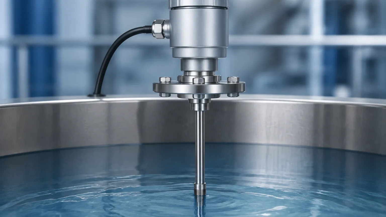
1. Avoid the Inflow Stream: Never install a capacitance level switch directly under a fill pipe. The falling material will cause intermittent switching and may physically damage the probe.
2. Grounding: For non-metallic (plastic or fiberglass) tanks, a ground reference must be provided. This is usually achieved by installing a dual-probe switch or a concentric ground tube (still-well).
3. Mounting Angle: While rod probes can be mounted horizontally or vertically, horizontal mounting should be slightly angled downwards to allow liquid to drain off the probe, reducing the risk of buildup.
4. Distance from Walls: Ensure the probe is not too close to the vessel wall or internal structures (like ladders or agitators). A minimum distance of 50 mm to 100 mm (2 to 4 inches) is generally recommended to prevent parasitic capacitance interference.
Common Risks and Limitations
While highly reliable, the capacitance level switch is not a "one-size-fits-all" solution. Awareness of its limitations prevents operational downtime:
* Changing Dielectric Constants: If a tank is used for multiple different products with widely varying $ε_r$ values, the switch may require re-calibration for each product. In such multi-product environments, radar or ultrasonic sensors might be more appropriate.
* Moisture Sensitivity: In dry bulk solids, a change in moisture content can significantly alter the dielectric constant. For example, dry sand has a lower $ε_r$ than wet sand. If the moisture level fluctuates, the switch may trigger at the wrong level.
* Heavy Coating: While active shield technology helps, extremely thick or viscous coatings (like bitumen or heavy grease) can eventually overcome the electronics' ability to compensate.
Frequently Asked Questions (FAQs)
Q: Can a capacitance level switch be used in a plastic tank?
A: Yes, but since the tank wall is not conductive, it cannot act as the second plate of the capacitor. You must use a switch with a ground reference electrode or install a metal plate/strip on the outside of the tank to act as the ground.
Q: How do I calibrate a capacitance switch?
A: Most modern switches feature a "teach-in" button. You typically calibrate the "empty" state (probe in air) and the "full" state (probe covered by material). Some advanced digital switches allow for calibration via a smartphone app or HART protocol.
Q: Is it possible to use these switches for continuous level measurement?
A: While this article focuses on point level switches, the same capacitance principle is used for continuous level transmitters. However, the electronics and output (4-20mA instead of a relay) differ.
Q: What is the impact of foam on the sensor?
A: Capacitance switches are generally sensitive to foam. Depending on the foam's density and conductivity, the switch may trigger when it hits the foam layer rather than the liquid level. If foam must be ignored, frequency shift or tuning fork switches may be better alternatives.
Summary and Next Steps
The capacitance level switch offers a durable and cost-effective solution for point level detection in industries ranging from wastewater treatment to chemical processing. Its success depends on matching the probe design and coating to the material's dielectric properties and the vessel's physical environment.
Before finalizing a project specification, engineers should confirm:
1. The minimum and maximum dielectric constant of the process media.
2. The presence of agitators or internal obstructions.
3. The likelihood of material buildup or coating on the probe.
4. The mounting requirements (thread size, flange type, and length).
For further technical specifications and to explore our full range of level measurement instruments, including radar and ultrasonic sensors, please visit our Main Page. Our engineering team is available to provide customized OEM/ODM services to meet specific industrial automation requirements.