Capacitive Fuel Level Sensor
Capacitive Fuel Level Sensor
In the realm of industrial fluid management and fleet logistics, the accurate measurement of fuel levels is a fundamental requirement for operational efficiency, cost control, and equipment longevity. Among the various technologies available, the capacitive fuel level sensor has emerged as a preferred solution for monitoring diesel, gasoline, and kerosene in both stationary storage tanks and mobile assets. This guide provides a detailed technical analysis of capacitive sensing technology, its application parameters, and the engineering considerations necessary for successful implementation.
Understanding the Measurement Principle
The operation of a capacitive fuel level sensor is based on the electrical property of capacitance. In its simplest form, a capacitor consists of two conductive plates separated by an insulating material known as a dielectric. The ability of this setup to store an electrical charge is defined by the formula:
**C = (ε₀ * εᵣ * A) / d**
Where:
* C is the capacitance.
* ε₀ is the permittivity of free space.
* εᵣ is the relative permittivity (dielectric constant) of the material between the plates.
* A is the area of the plates.
* d is the distance between the plates.
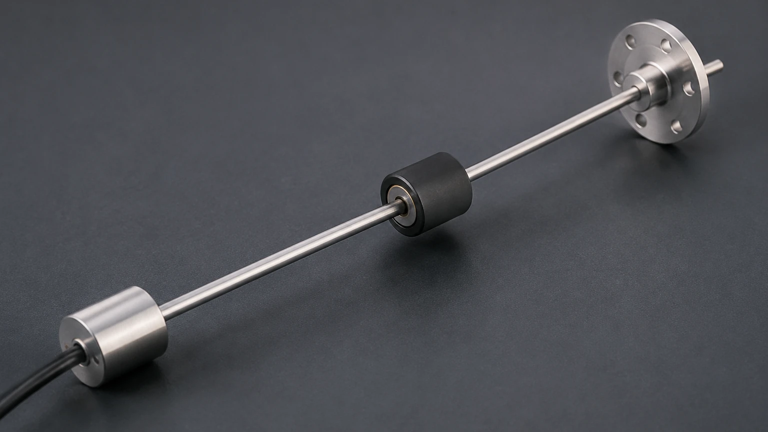
In a capacitive fuel level sensor, the probe typically consists of two concentric metal tubes (an inner electrode and an outer protective shield) or a single rod used in conjunction with a metallic tank wall. These conductive elements act as the capacitor plates. The fuel itself, along with the air or vapor space above it, serves as the dielectric material.
Because fuel (such as diesel) has a higher dielectric constant (εᵣ ≈ 2.1) than air (εᵣ ≈ 1.0), the total capacitance of the probe changes linearly as the fuel level rises and displaces the air between the electrodes. The integrated electronics in the sensor head convert this change in capacitance into a proportional electrical signal, such as 0-5V, 4-20mA, or digital RS485/RS232 protocols.
Key Advantages in Industrial and Fleet Applications
Capacitive sensors offer several distinct benefits over traditional mechanical float-based systems or alternative non-contact methods in specific fuel-related environments.
1. Solid-State Reliability
One of the most significant advantages is the absence of moving parts. Mechanical floats are susceptible to wear, sticking due to fuel varnish, or damage from high-vibration environments. Capacitive sensors are entirely solid-state, making them highly resistant to the mechanical stresses found in heavy machinery, locomotives, and long-haul trucks.
2. High Precision and Resolution
Capacitive technology allows for very high resolution, often detecting changes in fuel level as small as 1 mm (0.04 inches). This precision is critical for fuel theft detection and for calculating fuel consumption rates in real-time. Unlike ultrasonic sensors, which may struggle with surface foam or turbulence, capacitive probes measure the volume between the electrodes, providing a more stable reading in agitated tanks.
3. Customization and Adaptability
Many industrial capacitive fuel probes are designed to be "cut-to-length." This allows engineers to purchase a standard probe and trim it to the exact height of the tank during installation, simplifying inventory management for fleets with diverse tank sizes.
Technical Selection Criteria
Selecting the correct capacitive fuel level sensor requires an evaluation of the specific fuel chemistry and the physical environment of the tank. For a broader overview of industrial measurement technologies, including radar and ultrasonic options, engineers may Review product options and application support on the Welk main site.
Selection Table: Application Parameters
| Feature | Specification Range | Engineering Note |
| :— | :— | :— |
| Probe Length | 100 mm to 3000 mm | Can often be field-cut to fit tank height. |
| Output Signal | 4-20mA, 0-5V, RS485 | Digital outputs (RS485) are preferred for long distances. |
| Input Voltage | 9V – 36V DC | Must be compatible with vehicle or PLC power systems. |
| Inaccuracy | ±0.5% to ±1% FS | Includes linearity and hysteresis errors. |
| Temperature Range | -40°C to +85°C | Critical for outdoor or engine-room installations. |
| Material | Aluminum Alloy / Stainless Steel | Must be compatible with the fuel type (e.g., Ethanol). |
Installation and Calibration Best Practices
Proper installation is paramount to ensuring the accuracy of a capacitive sensor. Because the sensor relies on the dielectric properties of the medium, the physical mounting must be precise.
Mounting Location
The sensor should ideally be installed in the center of the tank to minimize the effects of fuel sloshing when the tank is tilted or in motion. If the tank contains internal baffles, the probe must be positioned away from them to prevent interference with the electrical field.
Grounding and Interference
In metal tanks, the tank itself can act as the reference ground. However, in plastic or composite tanks, a sensor with a dual-electrode design (a concentric outer tube) is mandatory to provide a stable reference. Ensuring a common ground between the sensor and the data acquisition system is essential to prevent signal noise.
Calibration Procedure
Most capacitive fuel sensors require a two-point calibration:
1. Zero Calibration (Empty): Performed when the probe is dry or the tank is empty. This sets the baseline capacitance for air.
2. Full Calibration (Span): Performed when the probe is fully immersed in the specific fuel being measured. This accounts for the specific dielectric constant of that fuel batch.
Advanced sensors feature "auto-calibration" or digital configuration via software, which allows for adjustments if the fuel type is changed (e.g., switching from standard diesel to a biodiesel blend).
Limitations and Environmental Factors
While highly effective, capacitive fuel level sensors have specific limitations that must be managed by the design engineer.
1. Dielectric Sensitivity
The most significant limitation is that the sensor is calibrated to a specific dielectric constant. If the fuel composition changes significantly—for example, if a high percentage of ethanol is added to gasoline—the sensor will report an inaccurate level because ethanol has a much higher dielectric constant than gasoline.
2. Water Contamination
Water has a dielectric constant of approximately 80, which is nearly 40 times higher than that of diesel. If water settles at the bottom of a fuel tank and reaches the sensor electrodes, the capacitance will spike, causing an erroneously high level reading or a sensor error. In applications where water ingress is common, sensors with specialized coatings or bottom-gap designs are used to mitigate this risk.
3. Tank Material Considerations
As noted previously, non-metallic tanks do not provide a conductive path. Engineers must ensure they select "three-wire" or concentric probe models specifically designed for non-conductive vessels to ensure the electrical field is contained within the probe assembly.
Comparison with Alternative Technologies
To provide context for selection, the following table compares capacitive sensors with other common level measurement technologies used in fuel applications.
| Technology | Best Use Case | Primary Limitation |
| :— | :— | :— |
| Capacitive | Fleet fuel monitoring, high vibration. | Sensitive to changes in fuel chemistry. |
| Hydrostatic | Deep stationary storage tanks. | Affected by fuel density changes. |
| Ultrasonic | Non-contact, corrosive liquids. | Can be affected by foam and tank internal structures. |
| Radar (GWR) | High-precision industrial process tanks. | Higher cost and complexity. |
| Magnetic Float | Simple, low-cost stationary monitoring. | Moving parts can fail or stick over time. |
For more information on the full spectrum of level measurement instruments, including radar level meters and ultrasonic sensors, visit the Main Page.
Frequently Asked Questions (FAQ)
Q: Can a capacitive fuel sensor be used for water-based liquids?
A: Yes, but the electronics must be designed for high-dielectric fluids. A sensor calibrated for fuel (dielectric ~2) will not work correctly in water (dielectric ~80) without recalibration and, often, different insulation on the probe to prevent short-circuiting.
Q: How does temperature affect the reading?
A: Fuel expands and contracts with temperature, and its dielectric constant also shifts slightly. High-quality capacitive sensors include internal temperature compensation to adjust the output signal automatically as the environment changes.
Q: Is it possible to cut the sensor probe?
A: Many industrial models are designed to be cut to length. However, this must be done according to the manufacturer's instructions, and a recalibration (Zero/Full) is always required after the probe has been shortened.
Q: What maintenance is required?
A: Because there are no moving parts, maintenance is minimal. However, in tanks with heavy sediment or "fuel bug" (microbial growth), the probe should be inspected annually and cleaned with a non-corrosive solvent to ensure the space between electrodes remains clear.
Conclusion
The capacitive fuel level sensor represents a robust, high-precision solution for modern fuel management. By understanding the dielectric properties of the fuel and ensuring proper installation and calibration, engineers can achieve reliable data even in the most demanding industrial environments. When selecting a system, always confirm the compatibility of the sensor materials with the specific fuel additives in use and consider the integration requirements of the end-user's monitoring platform.