Thermal Flowmeter
Thermal Flowmeter
In the landscape of industrial process control, the measurement of gas and liquid flow is as critical as monitoring tank levels. While level measurement provides data on volume and inventory, flow measurement ensures the efficiency of distribution and the accuracy of chemical dosing. Among the various technologies available, the thermal flowmeter—specifically the thermal mass flowmeter—has emerged as a preferred solution for gas applications due to its ability to measure mass flow directly without the need for additional pressure or temperature compensation. This guide provides a technical overview of thermal flowmeter principles, selection criteria, and installation best practices for engineering professionals.
Understanding the Principle of Thermal Mass Flow Measurement
Thermal flowmeters operate based on the thermal properties of the fluid being measured. Unlike volumetric flowmeters (such as vortex or turbine meters), which measure the space the fluid occupies, a thermal flowmeter measures the mass of the fluid passing a specific point. This is achieved by monitoring how heat is dissipated into the flow stream.
The most common design utilizes two Resistance Temperature Detectors (RTDs). One sensor serves as the reference, measuring the ambient temperature of the fluid. The second sensor is heated to a specific temperature above the reference. As the fluid flows past the heated sensor, it carries away heat—a process known as convective heat transfer.
There are two primary methods used to translate this heat loss into a flow measurement:
1. Constant Temperature Differential
In this method, the electronics maintain a constant temperature difference (ΔT) between the heated sensor and the reference sensor. As the mass flow rate increases, the cooling effect on the heated sensor becomes stronger. To maintain the constant ΔT, the instrument must increase the electrical power supplied to the heated sensor. This power consumption is directly proportional to the mass flow rate of the fluid.
2. Constant Power
In the constant power configuration, a fixed amount of electrical energy is supplied to the heated sensor. As the flow rate increases, the temperature of the sensor decreases due to the cooling effect. The temperature difference between the heated sensor and the reference sensor is measured, and this ΔT is inversely proportional to the mass flow rate. While this method is simpler, the constant temperature differential method is more common in modern industrial applications due to its wider turndown ratio and faster response time.
Mathematically, these principles are often described by King’s Law, which relates the heat loss from a heated wire to the fluid velocity ($v$) and density ($
ho$):
$$P = a + b(
ho v)^n$$
Where $P$ is the heater power, $a$ and $b$ are constants related to the fluid and sensor geometry, and $n$ is an exponent (typically around 0.5).
Key Components and Design Variations
Thermal flowmeters are generally categorized into two physical configurations depending on the application and pipe size:
* Capillary (Thermal Mass Flow Controllers): These are typically used for low-flow gas applications in laboratories or semiconductor manufacturing. A small portion of the flow is diverted through a bypass capillary tube where the measurement takes place.
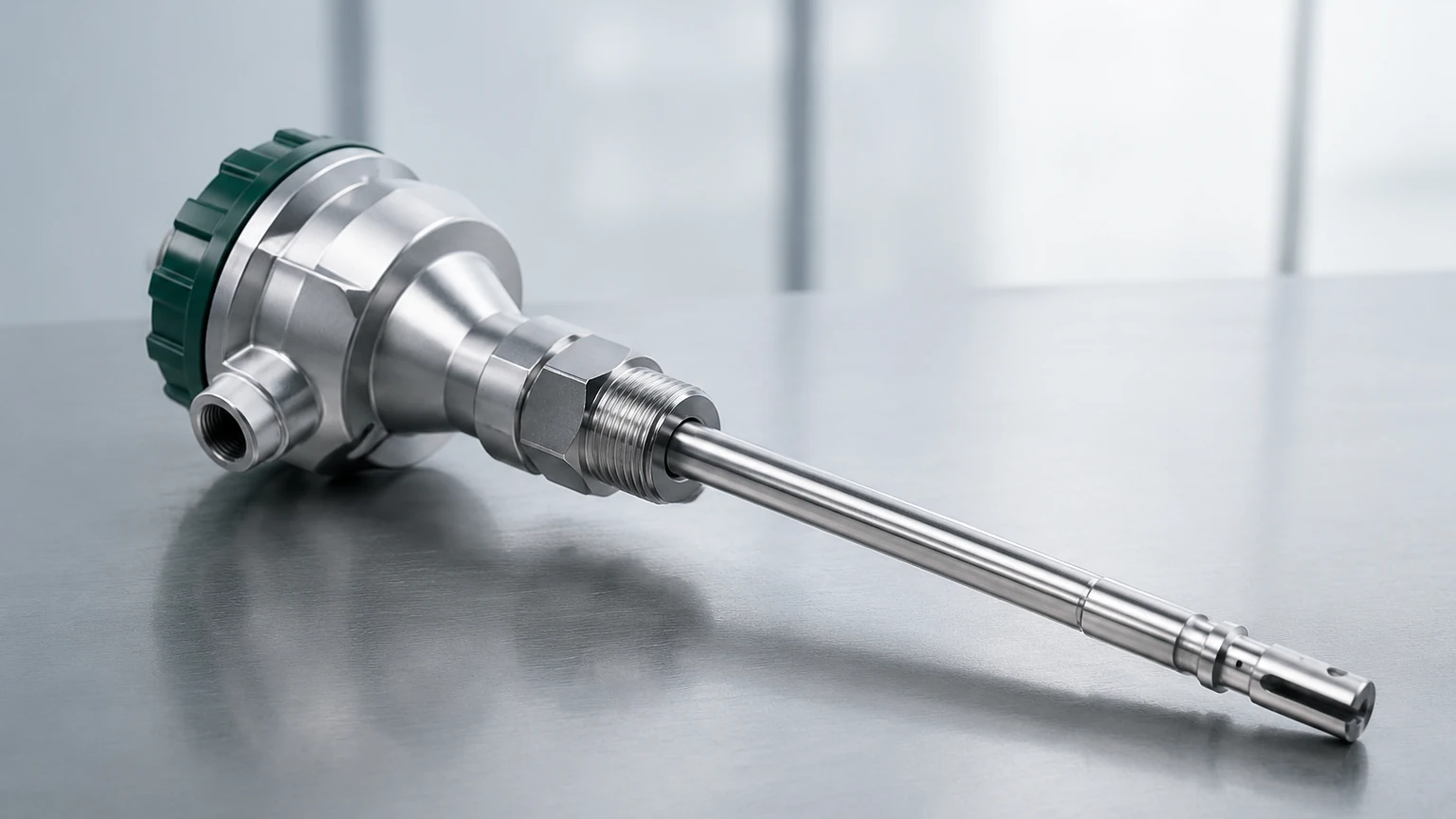
* Immersion/Insertion Meters: These are the standard for industrial B2B applications. The sensors are housed in a probe that is inserted directly into the process piping. For smaller pipes (typically below 50 mm), an in-line version is used where the sensors are pre-installed in a spool piece.
Industrial Selection Criteria for Thermal Flowmeters
Selecting the right thermal flowmeter requires a detailed understanding of the process fluid and the environment. Because these meters rely on heat transfer, the specific heat capacity ($C_p$) and thermal conductivity of the fluid must be known and constant. If the gas composition changes significantly, the calibration will no longer be accurate.
Selection Table: Comparison of Flow Technologies
| Feature | Thermal Flowmeter | Vortex Flowmeter | Differential Pressure (DP) |
| :— | :— | :— | :— |
| Primary Measurement | Mass Flow | Volumetric Flow | Differential Pressure |
| Media Type | Primarily Gases | Liquids, Gases, Steam | Liquids, Gases, Steam |
| Pressure Drop | Very Low | Medium | High |
| Turndown Ratio | High (up to 100:1) | Medium (20:1) | Low (5:1) |
| Moving Parts | None | None | None |
| Compensated? | Not required | Requires P/T sensors | Requires P/T sensors |
Critical Evaluation Factors
1. Gas Composition: Thermal flowmeters are calibrated for specific gases (e.g., Nitrogen, Compressed Air, Natural Gas). If the process involves a mixture, the exact percentages of each component must be provided to the manufacturer.
2. Flow Range: One of the greatest strengths of the thermal flowmeter is its ability to measure very low velocities, often down to 0.1 m/s. This makes them ideal for leak detection.
3. Process Temperature: Standard industrial models typically handle up to 200°C, though specialized high-temperature versions exist.
4. Moisture Content: Thermal meters are sensitive to water droplets. If a droplet hits the heated sensor, it causes a sudden "spike" in the reading as the sensor tries to evaporate the liquid. They are best suited for dry gas applications.
Installation Best Practices and Considerations
To achieve the stated accuracy (typically ±1% of reading), proper installation is paramount. Like most flow measurement technologies, thermal flowmeters require a fully developed flow profile.
Straight Run Requirements
Turbulence caused by elbows, valves, or reducers can distort the velocity profile. Generally, an insertion thermal flowmeter requires:
* Upstream: 15 to 20 diameters (D) of straight pipe.
* Downstream: 5 to 10 diameters (D) of straight pipe.
If these distances cannot be met, flow conditioners (honeycombs or perforated plates) can be installed to stabilize the flow, though this increases the pressure drop slightly.
Orientation and Mounting
For horizontal pipes, the sensor probe should ideally be installed at the 2 o'clock or 10 o'clock position. This prevents sediment at the bottom of the pipe or moisture/condensate at the top from interfering with the RTD sensors. For vertical pipes, the flow should ideally be upward to ensure a consistent profile.
Insertion Depth
For insertion-style meters, the sensor must be located at the point of average velocity. In most turbulent flow regimes within industrial piping, this is at the center of the pipe. Accurate measurement of the pipe's internal diameter is necessary to calculate the correct insertion depth.
Limitations and Operational Challenges
While highly effective, the thermal flowmeter is not a universal solution. Engineers should be aware of the following limitations:
* Fluid Properties: They are not suitable for liquids with high viscosity or fluids that may coat the sensor. Any buildup on the sensor probe acts as an insulator, reducing the heat transfer and causing the meter to under-read.
* Heat Transfer Variations: Changes in the gas composition change the thermal conductivity. For example, a meter calibrated for Air will read significantly higher if Hydrogen is introduced, as Hydrogen has a much higher thermal conductivity.
* Flow Velocity Limits: While excellent at low flows, they can lose accuracy at very high velocities where the cooling effect plateaus.
Applications in Process Industries
Thermal flowmeters are found in diverse sectors, often working alongside level measurement systems to provide a complete picture of plant efficiency. For comprehensive industrial measurement solutions, including level and flow, engineers often consult the Main Page of specialized manufacturers to ensure instrument compatibility.
1. Compressed Air Management: Monitoring the output of compressors and identifying leaks in the distribution network. Since compressed air is an expensive utility, the high turndown of thermal meters is invaluable.
2. Wastewater Treatment: Measuring the air flow in aeration basins. Precise control of oxygen levels is necessary for biological treatment processes.
3. Flare Gas Monitoring: Measuring waste gas sent to flares in refineries. Thermal meters are preferred here because they can handle the low pressures and varying flow rates typical of flare headers.
4. Natural Gas Sub-metering: Tracking gas consumption in different departments of a large manufacturing facility for cost accounting.
Frequently Asked Questions (FAQs)
Q: Does a thermal flowmeter need periodic recalibration?
A: Yes. While there are no moving parts to wear out, the sensors can drift over time due to environmental factors or minor coating. Annual calibration or a "field check" of the zero-point is recommended.
Q: Can I use a thermal flowmeter for steam?
A: Generally, no. The high moisture content and phase-change nature of steam make thermal mass measurement inaccurate. Vortex flowmeters are typically the preferred choice for steam.
Q: How does pressure affect the measurement?
A: One of the main advantages of thermal flowmeters is that they are relatively independent of pressure changes. Because they measure mass flow, a change in pressure (which changes density) is naturally accounted for by the change in the number of molecules carrying heat away from the sensor.
Q: What is the typical response time?
A: Industrial thermal mass flowmeters usually have a response time between 1 and 2 seconds. This is sufficient for most process control loops but may be too slow for high-speed batching applications.
Conclusion
The thermal flowmeter represents a sophisticated yet robust solution for gas mass flow measurement. By understanding the underlying physics of convective heat transfer and adhering to strict installation guidelines regarding straight pipe runs and gas composition, engineers can implement a measurement system that offers high reliability and low maintenance. When integrated into a broader process strategy—incorporating the high-quality radar and ultrasonic level sensors found on the Main Page—these instruments allow for precise control over industrial assets and resources.