Carbon Capture Solution
Carbon Capture Solution
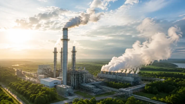
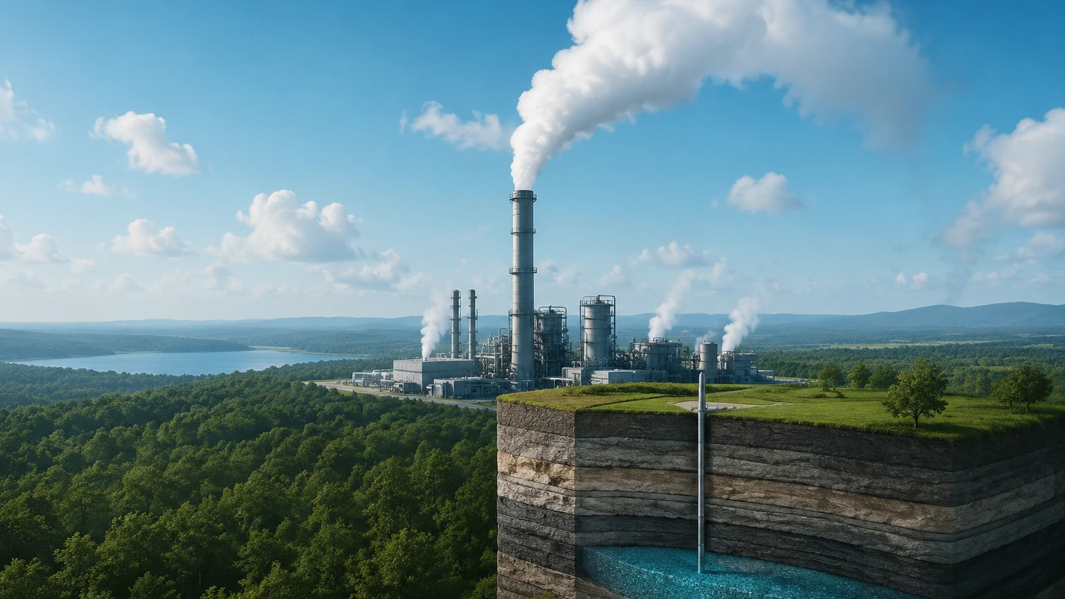
As global industrial sectors face increasing pressure to reduce greenhouse gas emissions, the implementation of a robust carbon capture solution has become a cornerstone of modern environmental engineering. Carbon Capture, Utilization, and Storage (CCUS) involves the capturing of carbon dioxide (CO2) from large point sources, such as power plants or industrial facilities, and either reusing it or storing it underground to prevent it from entering the atmosphere.
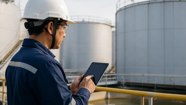
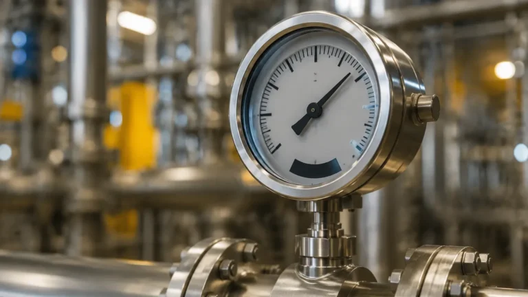
For engineers and plant managers, the success of a carbon capture solution depends heavily on the precision of process control. Level measurement is a critical component in this architecture, ensuring that the various chemical solvents, liquefied gases, and wastewater streams are managed safely and efficiently. This article explores the technical requirements for level instrumentation within carbon capture workflows, providing a practical guide for technology selection and installation.
Measurement Principles in Carbon Capture Environments
Before selecting instrumentation for a carbon capture solution, it is essential to understand the physical principles governing different measurement technologies. In CCS applications, the media can range from corrosive amine solvents to high-pressure liquefied CO2.
Radar Level Measurement (ToF)
Radar level meters operate on the Time-of-Flight (ToF) principle. They emit high-frequency microwave pulses that travel to the surface of the medium and reflect back to the sensor. The distance is calculated based on the time taken for the pulse to return. In carbon capture, non-contact radar is preferred for its ability to operate independently of pressure and temperature fluctuations. However, the dielectric constant (εr) of the medium is a critical factor; liquid CO2 has a low dielectric constant (approximately 1.6), which requires high-sensitivity radar units to ensure a reliable return signal.
Ultrasonic Level Measurement
Ultrasonic sensors emit sound waves that reflect off the liquid surface. While cost-effective for atmospheric water tanks within a carbon capture facility, they are generally not suitable for high-pressure CO2 storage or tanks with heavy vapor layers, as the speed of sound changes significantly with gas density and composition.
Hydrostatic Pressure Measurement
This principle relies on the relationship between the height of a liquid column and the pressure it exerts at the base (P = ρgh). Hydrostatic transmitters are frequently used in solvent storage tanks. In a carbon capture solution, these must be carefully calibrated for the specific gravity of the amine or carbonate solution, which may change with temperature and CO2 loading.
Magnetic Level Gauges
Magnetic gauges utilize a float containing a magnet that moves with the liquid level, actuating a visual indicator or a transmitter. These are highly valued in CCS for high-pressure vessels because they provide a clear visual reference without the risks associated with glass sight gauges.
Key Applications within a Carbon Capture Solution
A comprehensive carbon capture solution involves several distinct stages, each presenting unique challenges for level instrumentation.
1. Absorption and Stripping Columns
In post-combustion capture, CO2 is absorbed into a solvent (typically an amine-based solution). The absorber and stripper columns require precise level control to maintain the gas-to-liquid ratio.
* Challenge: Amine solutions tend to foam, which can cause false readings in some level sensors.
* Solution: Guided wave radar (GWR) or high-frequency non-contact radar is often recommended here, as they can penetrate or ignore foam layers more effectively than ultrasonic or traditional pressure sensors.
2. CO2 Liquefaction and Compression
Once captured, CO2 must be compressed and liquefied for transport. This process typically occurs at pressures exceeding 20 bar (290 PSI) and temperatures as low as -50°C (-58°F).
* Measurement Requirement: Instruments must be rated for cryogenic temperatures and high pressure. Magnetic level gauges or specialized radar transmitters with high-pressure seals are standard.
3. Buffer and Storage Tanks
Intermediate storage of captured CO2 and chemical reagents requires continuous monitoring. For large-scale storage, hydrostatic transmitters or non-contact radars provide the necessary accuracy for inventory management.
Technology Selection Table
Choosing the right instrument for a carbon capture solution requires balancing performance with environmental constraints. The following table provides a comparison of common technologies used in these applications.
| Technology | Typical Media | Max Pressure (Approx.) | Temperature Range | Pros | Cons |
| :— | :— | :— | :— | :— | :— |
| Non-Contact Radar | Liquid CO2, Solvents | 40+ bar | -196°C to +400°C | No moving parts; highly accurate. | Affected by very low dielectric constants. |
| Guided Wave Radar | Amine Solvents, Water | 400 bar | -200°C to +450°C | Excellent for foam and turbulent surfaces. | Probe is in contact with media; potential for coating. |
| Hydrostatic | Reagents, Wastewater | N/A (Head pressure) | -40°C to +100°C | Simple installation; cost-effective. | Sensitive to density changes. |
| Magnetic Gauge | Liquefied CO2 | 200+ bar | -196°C to +400°C | Visual local indication; robust. | Moving parts; float can get stuck if debris is present. |
Installation and Engineering Considerations
To ensure the longevity and accuracy of level sensors in a carbon capture solution, several installation factors must be addressed during the design phase.
Nozzle Placement and Stilling Wells
For radar installations, the nozzle should be positioned away from the tank wall and inlet pipes to avoid false reflections. In tanks with high turbulence or internal structures, the use of a stilling well (a vertical pipe that stabilizes the liquid surface) is recommended. This is particularly important when measuring liquid CO2, where the low dielectric constant makes the signal more susceptible to noise.
Chemical Compatibility
Carbon capture processes often involve aggressive chemicals like Monoethanolamine (MEA). All wetted parts of the level instrument—including flanges, seals, and probes—must be constructed from compatible materials such as 316L Stainless Steel, Hastelloy, or PTFE. For more information on material compatibility and instrument options, you can Review product options and application support to find solutions tailored to corrosive environments.
Pressure and Temperature Sealing
In the compression stage of a carbon capture solution, the risk of CO2 leakage is a significant safety concern. Level transmitters should utilize dual-seal designs or hermetically sealed housings to prevent process gas from entering the electronics housing or escaping into the atmosphere.
Limitations and Common Risks
While modern instrumentation is highly advanced, certain factors can compromise the effectiveness of a carbon capture solution:
1. Phase Changes: CO2 can exist in gas, liquid, or supercritical states depending on the pressure and temperature. Level meters must be selected based on the specific phase present in the vessel. Measuring the level of a supercritical fluid is technically impossible as there is no distinct liquid-gas interface; in these cases, mass flow or pressure-based density measurement is used instead.
2. Foaming: In amine scrubbers, foaming can lead to "level swell," where the actual liquid level is much lower than the foam top. This can cause pump cavitation or process upsets. Using radar with advanced signal processing can help distinguish between the foam and the true liquid level.
3. Build-up and Scaling: Some carbon capture processes involve mineral carbonation, which can lead to scaling on probes. Frequent maintenance or the use of non-contact sensors is necessary to prevent measurement drift.
Frequently Asked Questions (FAQs)
Q: Can I use a standard ultrasonic sensor for liquid CO2 storage?
A: Generally, no. The high-pressure CO2 vapor space above the liquid significantly alters the speed of sound, leading to massive errors. Radar or hydrostatic sensors are much more reliable for this application.
Q: How does the dielectric constant affect radar measurement in CCS?
A: The dielectric constant (εr) determines how much of the radar signal is reflected. Liquid CO2 has a very low εr, meaning most of the signal passes through it rather than reflecting. High-sensitivity radars with large antennas or guided wave radars are required to capture the weak reflection.
Q: What is the best way to measure level in a high-pressure absorber column?
A: Guided Wave Radar (GWR) is often the best choice because the probe guides the signal directly to the surface, overcoming the challenges of vapor, foam, and high pressure that might scatter a non-contact signal.
Conclusion
Implementing an effective carbon capture solution requires more than just chemical expertise; it demands precision engineering at the instrumentation level. By understanding the measurement principles of radar, hydrostatic, and magnetic sensors, and by accounting for the unique properties of CO2 and its solvents, operators can ensure their CCS facilities run safely and at peak efficiency. For those seeking technical specifications and high-performance hardware, visiting the Main Page of a specialized manufacturer like Welk provides access to the necessary tools for industrial-grade level measurement.