Carbon Catchers
Carbon Catchers
Carbon capture and storage (CCS) technology has transitioned from a niche industrial concept to a cornerstone of global decarbonization strategies. Often referred to colloquially as "carbon catchers," these systems are engineered to intercept carbon dioxide (CO2) emissions at the source—such as power plants or chemical refineries—before they reach the atmosphere. For process engineers and plant operators, the success of these systems depends heavily on the precise management of fluids, solvents, and liquefied gases.
In the complex cycle of capturing, compressing, transporting, and storing CO2, level measurement serves as a critical diagnostic and control parameter. Without accurate level data, the efficiency of absorption towers drops, the risk of pump cavitation increases, and the safety of high-pressure storage vessels can be compromised. This guide examines the technical requirements for level instrumentation within carbon catchers and provides a framework for selecting the right technology for these demanding environments.
The Role of Level Measurement in Carbon Capture Systems
Carbon catchers typically operate in three distinct phases: capture, compression/liquefaction, and storage. Each phase presents unique physical challenges for level sensors.
1. The Capture Phase (Absorption and Stripping)
In post-combustion capture, flue gas is passed through an absorption column containing a chemical solvent, often an amine-based solution. The solvent reacts with the CO2 to "catch" it. The level of the solvent in the bottom of the absorber and the subsequent stripper column must be maintained within tight tolerances. If the level is too high, it leads to liquid carryover; if it is too low, the pump may run dry, leading to mechanical failure.
2. Compression and Liquefaction
Once the CO2 is stripped from the solvent, it must be compressed and often liquefied for transport. This involves multi-stage compressors and flash tanks. Level sensors in these separators must handle rapidly changing pressures and the potential for phase changes between gaseous and liquid CO2.
3. Storage and Sequestration
Liquid CO2 is stored in large, insulated tanks or injected into deep geological formations. Monitoring the inventory in these tanks requires high-precision instruments that can operate at cryogenic temperatures or under extreme high-pressure conditions (often exceeding 70 bar).
Measurement Principles for CCS Applications
Before selecting an instrument for carbon catchers, it is essential to understand the physics behind the measurement. Industrial level measurement relies on several distinct principles, each with specific advantages in the context of CO2 handling.
Radar Level Measurement (ToF)
Radar sensors utilize the Time-of-Flight (ToF) principle. The device emits a high-frequency electromagnetic pulse that travels to the product surface and reflects back to the sensor. The distance is calculated based on the time interval and the speed of light.
* Non-Contact Radar: Ideal for corrosive solvents used in carbon catchers because the sensor does not touch the media. However, liquid CO2 has a low dielectric constant (εr ≈ 1.6), which results in weak signal reflection. High-frequency radar (80 GHz) is typically required to focus the beam and capture these faint echoes.
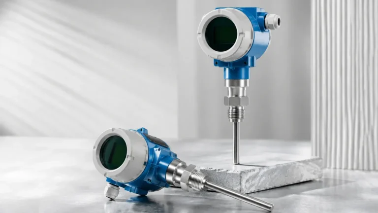
* Guided Wave Radar (GWR): Uses a physical probe (cable or rod) to guide the microwave pulse. This concentrates the energy, making it much more effective for low-dielectric liquids like CO2 and reducing the impact of foam or turbulence in absorption towers.
Ultrasonic Level Measurement
Ultrasonic sensors emit sound waves that reflect off the liquid surface. While cost-effective for water treatment, they are rarely used in the high-pressure stages of carbon catchers. Since sound requires a medium to travel, changes in gas density or the presence of heavy CO2 vapors can significantly alter the speed of sound, leading to large measurement errors.
Hydrostatic Pressure
This principle measures the pressure exerted by the liquid column (P = ρgh, where ρ is density, g is gravity, and h is height). In carbon catchers, hydrostatic transmitters are often used in solvent tanks. However, because CO2 density changes drastically with temperature and pressure, these systems require sophisticated compensation to remain accurate.
Magnetic Level Gauges (MLG)
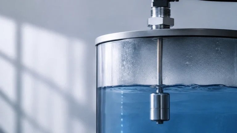
MLGs consist of a bypass chamber attached to the vessel. A float containing a magnet moves with the liquid level, flipping external flags or interacting with a magnetostrictive transmitter. This provides a clear visual indication and a redundant electronic signal, which is highly valued for safety-critical storage tanks.
Selecting Level Instruments for Carbon Catchers
Selecting the appropriate technology requires a detailed analysis of the process media and the environmental conditions. The following table provides a general selection framework for common CCS assets.
| Application | Media | Typical Pressure | Temp. Range | Recommended Technology |
| :— | :— | :— | :— | :— |
| Absorber Sump | Amine Solvent | 1–5 bar | 40°C to 60°C | Guided Wave Radar or Non-contact Radar |
| Stripper Column | Rich Amine | 1–3 bar | 100°C to 120°C | Guided Wave Radar (High Temp version) |
| Flash Tank | Liquid CO2 | 20–70 bar | -20°C to 30°C | Guided Wave Radar or Magnetic Level Gauge |
| Storage Tank | Liquefied CO2 | 15–25 bar | -30°C to -10°C | Magnetic Level Gauge with Transmitter |
| Condensate Pot | Water/CO2 mix | Up to 100 bar | Ambient | Hydrostatic or Differential Pressure |
For engineers looking for specific hardware configurations and technical datasheets, it is advisable to consult a professional manufacturer. You can Review product options and application support to find instruments tailored for high-pressure gas applications.
Installation and Engineering Considerations
The physical installation of a level meter in a carbon capture system is as important as the technology itself. Improper placement can lead to "ghost echoes" or mechanical damage.
1. Nozzle Geometry: For radar installations, the nozzle height and diameter must be optimized. If a nozzle is too long and narrow, the radar signal may reflect off the nozzle walls before reaching the media.
2. Stilling Wells: In vessels with high turbulence or foam (common in amine absorbers), installing the radar inside a stilling well (a perforated pipe) can protect the signal and provide a stable surface for measurement.
3. Pressure Seals: Carbon catchers often operate at high pressures. Instruments must be equipped with secondary process seals (such as glass-to-metal seals) to prevent hazardous CO2 leaks into the electronics housing in the event of a primary seal failure.
4. Material Compatibility: Amine solvents can be aggressive. Wetted parts, including probes and O-rings, should be constructed from 316L Stainless Steel, Hastelloy, or specialized polymers like Kalrez to ensure long-term reliability.
Limitations and Challenges in CO2 Level Monitoring
Despite advances in sensor technology, carbon catchers present several persistent challenges:
* Supercritical State: CO2 enters a supercritical state at 73.8 bar and 31.1°C. In this state, the boundary between liquid and gas disappears. Standard level measurement technologies that rely on a surface interface (like radar or floats) will fail to provide a reading because the interface no longer exists.
* Boiling and Flashing: In CO2 liquefaction, the liquid is often near its boiling point. Any slight drop in pressure can cause the liquid to flash into gas, creating bubbles that interfere with ultrasonic and radar signals.
* Dielectric Shifting: The dielectric constant of CO2 changes with its density. In high-pressure gas phases, the "gas phase compensation" feature on advanced Guided Wave Radar units is necessary to correct for the slowing of the microwave signal as it passes through dense CO2 vapor.
Frequently Asked Questions (FAQs)
Q: Can I use a standard ultrasonic sensor for liquid CO2 storage?
A: Generally, no. The high pressure and the density of the CO2 vapor above the liquid significantly alter the speed of sound, making ultrasonic measurements highly inaccurate. Radar or magnetic level gauges are the industry standard for these applications.
Q: Why is Guided Wave Radar (GWR) preferred over Non-contact Radar in amine strippers?
A: Amine strippers often involve steam and turbulence. GWR uses a physical probe that acts as a waveguide, ensuring the signal reaches the surface and returns reliably, even when steam or foam is present in the headspace.
Q: How do I handle level measurement if the CO2 is in a supercritical state?
A: In supercritical applications, "level" measurement is replaced by mass or density measurement. Technologies like Coriolis flow meters or nuclear (gamma) densitometers are used because they do not require a physical interface between phases.
Conclusion
As the deployment of carbon catchers scales globally, the demand for robust, high-precision level measurement will only grow. Engineers must look beyond simple "off-the-shelf" solutions and consider the specific thermodynamic properties of CO2 and the chemical nature of the solvents involved. By prioritizing technologies like Guided Wave Radar and Magnetic Level Gauges, and by adhering to strict installation standards, operators can ensure the long-term efficiency and safety of their carbon capture assets.
For further technical specifications and to explore a range of industrial measurement solutions, visit the Main Page of our product catalog. Selecting the right instrument today ensures the operational integrity of the decarbonization infrastructure of tomorrow.