Cerabar
Cerabar
In the landscape of industrial automation, pressure transmitters such as the Cerabar series represent a critical component for monitoring process variables. These instruments are designed to measure absolute and gauge pressure in liquids, vapors, and gases across various industrial sectors. Beyond simple pressure monitoring, these devices are frequently utilized for hydrostatic level measurement, providing a reliable method for determining the volume or mass of contents within a vessel.
Understanding the technical nuances of Cerabar technology—ranging from sensor construction to application-specific selection—is essential for process engineers and plant managers aiming to optimize efficiency and safety. As a professional manufacturer, Welk provides a broad spectrum of industrial level measurement instruments that complement these pressure-based solutions, ensuring comprehensive coverage for diverse operational requirements.
Principles of Pressure-Based Level Measurement
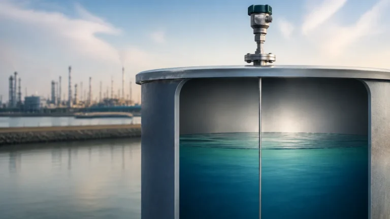
Hydrostatic level measurement is based on the principle that the pressure at a specific depth in a stationary liquid is proportional to the height of the liquid column above it. This relationship is defined by the formula:
P = ρ × g × h
Where:
* P is the hydrostatic pressure (Pa or bar).
* ρ (rho) is the density of the medium (kg/m³).
* g is the gravitational constant (approximately 9.81 m/s²).
* h is the height of the liquid (m).
Absolute vs. Gauge Pressure
In industrial applications, transmitters like the Cerabar series are configured to measure either absolute or gauge pressure:
1. Gauge Pressure: The sensor measures pressure relative to the atmospheric pressure. This is the most common method for level measurement in vented (open) tanks, where the atmospheric pressure acts on both the liquid surface and the reference side of the sensor diaphragm.
2. Absolute Pressure: The sensor measures pressure relative to a perfect vacuum. This is typically used in vacuum-rated processes or where atmospheric fluctuations might interfere with high-precision measurements.
For pressurized vessels, a differential pressure (DP) approach is required. In these scenarios, two pressure points are measured—one at the bottom of the tank and one in the gas phase at the top—to subtract the head pressure from the total pressure, isolating the hydrostatic pressure exerted by the liquid alone.
Sensor Technologies: Ceramic vs. Metallic Diaphragms
One of the defining characteristics of the Cerabar line is the choice between different sensor cell technologies. The selection of the diaphragm material is the most significant factor in determining the instrument's longevity and accuracy within a specific chemical environment.
Ceramic Sensors (Ceraphire)
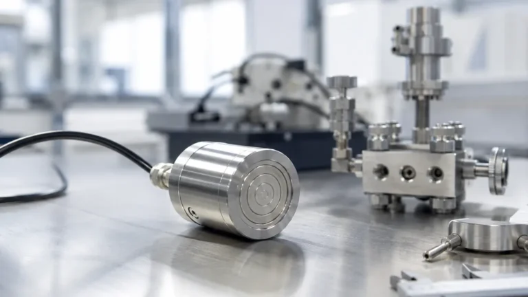
Ceramic sensors, often constructed from high-purity aluminum oxide (99.9% Al2O3), are "dry" cells. This means they do not require an internal fill fluid (such as silicone oil) to transmit pressure to the electronic transducer.
* Advantages: Ceramic is exceptionally hard and resistant to corrosion and abrasion. It can withstand high vacuum conditions and significant overpressure (up to 40 times the nominal range in some configurations). Because there is no fill fluid, there is no risk of process contamination should the diaphragm fail.
* Applications: Ideal for abrasive slurries, corrosive chemicals, and vacuum applications where oil-filled sensors might outgas or fail.
Metallic Sensors
Metallic sensors utilize a thin metal diaphragm (typically 316L stainless steel, Hastelloy, or Monel) coupled with a fill fluid. The pressure deforms the diaphragm, and the fluid transmits this force to a silicon or capacitive sensing element.
* Advantages: Metallic diaphragms are better suited for extremely high-pressure ranges (exceeding 400 bar) and applications requiring hygienic fittings, as the diaphragms can be made flush with the process connection to prevent bacterial growth.
* Applications: High-pressure steam lines, hygienic food and beverage processes, and oil and gas pipelines.
Selection Criteria for Industrial Applications
Choosing the correct pressure transmitter requires a detailed analysis of the process conditions. The following table provides a practical guide for evaluating Cerabar-type instruments against common industrial variables.
Practical Selection Table
| Process Variable | Recommended Sensor Type | Rationale |
| :— | :— | :— |
| Abrasive Slurries | Ceramic | High hardness prevents erosion of the diaphragm surface. |
| High Vacuum | Ceramic | Dry cell construction eliminates oil outgassing and diaphragm collapse. |
| Hygienic/Sanitary | Metallic (Flush) | Flush-mounted metallic diaphragms eliminate dead space and meet EHEDG/3-A standards. |
| High Temperature (>150°C) | Metallic with Capillaries | Remote seals and capillaries protect the electronics from extreme heat. |
| Hydrogen Service | Gold-Plated Metallic | Prevents hydrogen atoms from permeating the diaphragm and forming bubbles in the fill fluid. |
| Corrosive Acids | Ceramic or Tantalum | Ceramic offers broad chemical compatibility; Tantalum is used for aggressive metallic requirements. |
When evaluating these options, engineers should also consider the required accuracy class. Standard industrial transmitters often offer 0.075% or 0.05% accuracy of the calibrated span, which is sufficient for most inventory control and process regulation tasks. For a broader look at how these pressure-based systems compare to other technologies like radar or ultrasonic sensors, users can refer to the Main Page for a comprehensive technology overview.
Installation and Commissioning Best Practices
Proper installation is paramount to ensuring the accuracy and reliability of a Cerabar transmitter. Even the most advanced sensor will provide erroneous data if mounting conditions are neglected.
Mechanical Installation
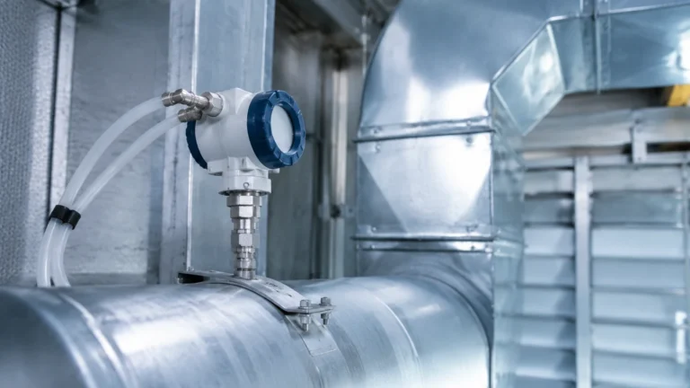
1. Mounting Position: For liquid applications, the transmitter should ideally be installed below the tapping point to ensure the impulse line remains filled with liquid and free of gas bubbles. For gas applications, the transmitter should be mounted above the tapping point so that condensate drains back into the process.
2. Impulse Lines: Keep impulse lines as short as possible. For high-temperature processes, a siphon or cooling leg should be used to protect the sensor from direct contact with hot vapors.
3. Venting: Ensure the reference side of gauge pressure transmitters is properly vented to the atmosphere, typically through a specialized cable or a Gore-Tex filter, to prevent pressure offsets caused by weather changes.
Electrical and Digital Integration
Modern transmitters are rarely standalone devices. They typically support 4-20 mA HART, Profibus PA, or FOUNDATION Fieldbus protocols.
* HART Communication: Allows for remote configuration and diagnostics. It is essential to ensure the loop resistance is between 250 and 600 ohms for stable HART communication.
* Grounding: Proper grounding of the housing and cable shield is necessary to prevent electromagnetic interference (EMI) from variable frequency drives (VFDs) and other heavy machinery.

Limitations and Common Risks
While Cerabar transmitters are robust, they are not universal solutions. Engineers must be aware of specific limitations:
* Density Fluctuations: Since hydrostatic measurement depends on density (ρ), any change in the liquid's temperature or composition that alters its density will result in a level error. If density varies significantly, a displacement or radar-based system may be more appropriate.
* Hydrogen Permeation: In applications involving hydrogen gas, small hydrogen ions can diffuse through standard metallic diaphragms. This leads to the formation of hydrogen gas bubbles in the internal fill fluid, causing a "zero shift" or total sensor failure. Gold plating is the standard mitigation strategy.
* Temperature Shocks: Rapid changes in process temperature (thermal shock) can cause temporary measurement errors as the sensor and fill fluid equilibrate. Ceramic sensors generally handle thermal shocks better than oil-filled metallic sensors, but both have limits specified in their technical data sheets.
* Build-up and Clogging: In viscous or crystallizing media, the process connection or impulse line can clog. Flush-mounted diaphragms are recommended for these environments to minimize maintenance requirements.
Frequently Asked Questions (FAQs)
Q: How often should a Cerabar pressure transmitter be calibrated?
A: While many modern transmitters offer excellent long-term stability (e.g., 0.1% per 5-10 years), the calibration interval depends on the criticality of the process and local regulations. A typical interval for non-critical processes is 2 to 3 years, while safety-instrumented systems (SIS) may require annual verification.
Q: Can I use a pressure transmitter for interface measurement?
A: Yes, if the two liquids have distinct and constant densities. The transmitter measures the total hydrostatic head, and if the total level is kept constant (or measured by a second device), the height of the interface can be calculated.
Q: What is the "Turn-down" ratio?
A: Turn-down refers to the ratio between the maximum sensor range and the calibrated span. For example, a 10-bar sensor used to measure a 1-bar range has a 10:1 turn-down. High turn-down ratios (up to 100:1) allow for inventory flexibility but may slightly decrease accuracy at the lower end of the scale.
Q: Is it possible to use these sensors in explosive atmospheres?
A: Yes, Cerabar transmitters are available with various explosion-proof and intrinsically safe certifications, such as ATEX, IECEx, and FM. Always verify that the device marking matches the zone classification of the installation site.
Conclusion and Technical Confirmation
Implementing a Cerabar transmitter for pressure or level measurement requires a balance between sensor technology, material compatibility, and installation precision. By selecting the appropriate diaphragm—ceramic for abrasion and vacuum, or metallic for high pressure and hygiene—operators can ensure long-term stability in their process loops.
Before proceeding with a procurement or installation project, technical teams should confirm the following:
1. The chemical compatibility of the wetted parts with the process media.
2. The maximum possible overpressure and vacuum conditions the sensor might encounter.
3. The density stability of the medium if using the device for level measurement.
4. The requirements for digital integration into the existing PLC or DCS architecture.
For industrial facilities seeking a wider range of level solutions, including specialized radar, ultrasonic, and magnetic gauges, exploring the Main Page provides the necessary context to select the most cost-effective and accurate technology for any given application. Welk remains committed to providing the technical support and high-quality instrumentation required for modern industrial automation.