Clamp Flow Meter
Clamp Flow Meter
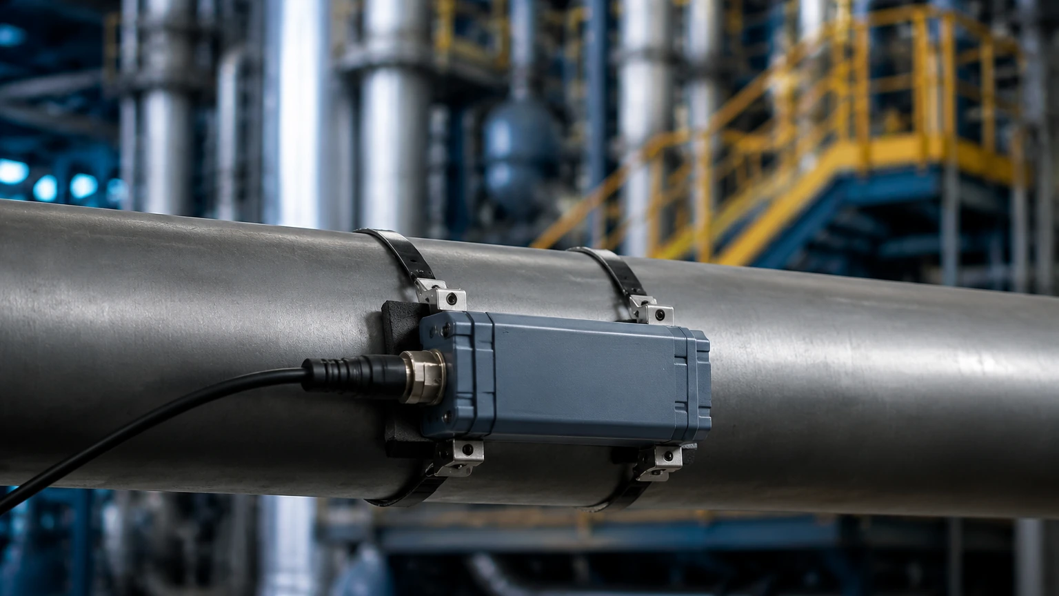
In modern industrial process control, the ability to measure fluid dynamics without interrupting production or compromising the integrity of the piping system is a significant operational advantage. The clamp flow meter, specifically the ultrasonic variety, has become a cornerstone technology for engineers managing water treatment, chemical processing, and oil and gas facilities. Unlike traditional inline meters that require pipe cutting and flange installation, clamp-on devices offer a non-invasive solution that maintains the primary containment of the process fluid.
Understanding the engineering principles, selection criteria, and installation nuances of these instruments is essential for ensuring accurate data acquisition. This guide provides a technical overview of clamp-on ultrasonic flow measurement and its integration into broader process monitoring systems, such as those found on our Main Page.
Measurement Principles: Transit-Time vs. Doppler
Before selecting a clamp flow meter, it is vital to understand the two primary ultrasonic measurement principles. Both rely on the transmission of high-frequency sound waves through the pipe wall and the fluid, but they process the signal differently based on the fluid's characteristics.
Transit-Time Ultrasonic Technology
Transit-time meters are the most common type used in industrial applications. This method utilizes a pair of transducers that function as both transmitters and receivers. They are mounted on the outside of the pipe at a specific distance from each other.
The principle is based on the time difference ($Δt$) it takes for an ultrasonic pulse to travel between the two transducers. A pulse traveling with the flow (downstream) moves faster than a pulse traveling against the flow (upstream). The electronics calculate the flow velocity based on this time difference, the pipe diameter, and the path length. This technology is exceptionally accurate for clean liquids with low concentrations of suspended solids or entrained gases (typically less than 2% by volume).
Doppler Effect Technology
Doppler flow meters operate by transmitting an ultrasonic signal into the fluid and measuring the frequency shift of the signal reflected off moving discontinuities. These discontinuities can be suspended solids, slurry particles, or entrained gas bubbles.
According to the Doppler principle, the frequency of the reflected signal is shifted in proportion to the velocity of the particles in the fluid. While Doppler meters are generally less accurate than transit-time meters (often within 2% to 5% of the actual flow), they are indispensable for "dirty" liquids, wastewater, and thick slurries where a transit-time signal would be completely attenuated or blocked.
Selection Criteria for Industrial Applications
Choosing the correct clamp flow meter requires a detailed analysis of the application environment. The following table outlines the primary considerations when evaluating these technologies:
| Criteria | Transit-Time Meter | Doppler Meter |
| :— | :— | :— |
| Fluid Type | Clean liquids (water, oils, chemicals) | Slurries, wastewater, aerated liquids |
| Solid Content | < 2% by volume | > 100 ppm of particles > 75 microns |
| Pipe Material | Metal, plastic, glass (homogenous) | Most materials, provided sound transmits |
| Accuracy | ±0.5% to ±2% of reading | ±2% to ±5% of full scale |
| Flow Velocity | 0.01 to 12 m/s | 0.1 to 10 m/s |
| Primary Use | Energy audits, water distribution | Mining, sewage, dredging |
Pipe Material and Liners
The material of the pipe wall significantly influences ultrasonic signal propagation. Homogenous materials like carbon steel, stainless steel, and PVC are ideal. However, pipes with internal liners (such as rubber, cement, or PTFE) present challenges. If the liner is not perfectly bonded to the pipe wall, an air gap can form, which reflects the ultrasonic signal and prevents measurement. Engineers must confirm the liner type and bonding quality before finalizing a selection.
Installation Engineering and Transducer Mounting
The performance of a clamp flow meter is heavily dependent on the quality of the installation. Unlike level measurement instruments like radar or ultrasonic level sensors, which are typically mounted at the top of a vessel, flow transducers must be precisely positioned on the pipe circumference.
Mounting Methods (V, W, and Z)
There are three standard configurations for mounting transducers:
1. V-Method: This is the standard installation for pipe diameters ranging from 25 mm to 400 mm. The transducers are placed on the same side of the pipe, and the signal bounces once off the opposite wall. It provides a good balance between signal strength and accuracy.
2. W-Method: Used for small-diameter pipes (usually under 50 mm). The signal bounces three times before reaching the receiver, effectively increasing the path length and improving measurement resolution for very small volumes.
3. Z-Method: Preferred for large-diameter pipes (over 400 mm) or pipes with high attenuation (e.g., cast iron or pipes with scale buildup). The transducers are mounted on opposite sides of the pipe, and the signal crosses the fluid path only once.
Pipe Preparation and Coupling
To ensure the ultrasonic signal enters the pipe wall without loss, the mounting surface must be prepared. This involves removing rust, loose paint, or heavy scale to reach a smooth, flat surface. A coupling compound (acoustic gel or grease) is applied between the transducer face and the pipe wall to eliminate air gaps. In permanent installations, solid coupling pads or specialized epoxies may be used to ensure long-term signal stability.
Straight Pipe Requirements
To achieve the specified accuracy, the flow profile must be fully developed and stable. This requires a minimum length of straight pipe upstream and downstream of the installation point. A general engineering rule is 10D (ten times the pipe diameter) of straight run upstream and 5D downstream from any disturbance like elbows, valves, or pumps. If these conditions cannot be met, the meter's accuracy may degrade, or specialized flow conditioners may be required.
Limitations and Common Risks
While the clamp flow meter is highly versatile, it is not a universal solution. Engineers should be aware of the following limitations:
* Aeration and Bubbles: In transit-time meters, even a small percentage of entrained air can scatter the ultrasonic beam, leading to a "signal lost" error. This is common in suction lines or gravity-fed systems.
* Wall Thickness Uncertainty: The meter calculates flow based on the internal diameter. If the actual wall thickness differs from the nominal value due to corrosion or manufacturing tolerances, the resulting flow calculation will be biased. Using an ultrasonic thickness gauge prior to installation is recommended.
* Temperature Extremes: Standard transducers are often rated up to 120°C. For high-temperature applications (e.g., steam condensate or hot thermal oil), specialized high-temperature transducers and mounting hardware are necessary to prevent sensor failure.
* Signal Attenuation: Certain materials, such as fiberglass or old cast iron with heavy internal tuberculation, absorb ultrasonic energy, making it difficult to obtain a reliable signal.
Integration with Level Measurement Systems
In many industrial processes, flow data is combined with level data to provide a comprehensive view of the system's mass balance. For instance, in a chemical storage tank application, an ultrasonic or radar level meter (details of which can be found on our Main Page) monitors the inventory volume, while a clamp flow meter on the discharge line monitors the rate of consumption.
This dual-monitoring approach allows for:
* Leak Detection: Comparing the change in tank level against the integrated flow volume over time.
* Pump Control: Using flow rates to verify pump performance and prevent dry-running based on low-level alerts.
* Process Optimization: Ensuring that inflow and outflow rates are balanced to maintain steady-state operations in continuous reactors or water treatment basins.
Frequently Asked Questions (FAQ)
Q: Can a clamp flow meter measure gas flow?
A: While most industrial clamp-on meters are designed for liquids, specialized high-power ultrasonic meters exist for gas applications. However, they require much higher signal processing capabilities due to the low density of gas and the high acoustic impedance mismatch between the pipe wall and the gas.
Q: How often does a clamp-on meter need calibration?
A: Since there are no moving parts and no contact with the fluid, the electronic components are very stable. However, the coupling gel can dry out over time. It is recommended to inspect the signal strength annually and perform a field verification against a master meter or via a volumetric draw-down test every 2-3 years.
Q: Does pipe orientation matter?
A: Yes. For horizontal pipes, transducers should be mounted at the 3 o'clock and 9 o'clock positions. Mounting at the top (12 o'clock) risks signal interference from air pockets, while mounting at the bottom (6 o'clock) risks interference from settled sediment. For vertical pipes, flow should ideally be in the upward direction to ensure the pipe remains full.
Conclusion
The clamp flow meter represents a highly efficient, cost-effective, and safe method for industrial fluid measurement. By eliminating the need for process downtime and potential leak points associated with inline meters, it provides a flexible tool for both permanent installation and temporary diagnostic audits. When combined with reliable level measurement instruments, these devices form the backbone of modern industrial automation and resource management. For more information on comprehensive measurement solutions, including radar and ultrasonic level sensors, please visit our Main Page.