Coastal Flow Liquid Measurement
Coastal Flow Liquid Measurement
Coastal flow liquid measurement represents one of the most challenging subsets of industrial instrumentation. Whether managing seawater intake for desalination plants, monitoring wastewater discharge into estuaries, or supervising liquid cargo transfers at marine terminals, the intersection of hydraulic engineering and environmental resilience is critical. In these environments, accuracy is not merely a matter of process efficiency; it is essential for regulatory compliance and the protection of sensitive marine ecosystems.
Effective coastal flow liquid measurement requires an integrated approach that accounts for high salinity, fluctuating ambient temperatures, and the physical turbulence inherent in coastal geography. This article examines the core technologies, selection criteria, and installation best practices for liquid measurement in coastal and marine applications.
Understanding the Relationship Between Level and Flow
In most coastal applications, flow is measured using indirect methods, specifically through the relationship between the level (head) of a liquid and its velocity or volume through a known geometry. This is particularly true for open-channel systems such as drainage canals or cooling water outfalls.
The Principle of Open Channel Measurement
Open channel flow measurement relies on primary devices—such as flumes or weirs—that restrict the flow and create a predictable relationship between the liquid level and the flow rate. The formula generally follows the structure of $Q = C \times H^n$, where $Q$ is the flow rate, $C$ is a discharge coefficient, $H$ is the head (level), and $n$ is an exponent based on the device geometry.
To automate this, a level sensor is mounted above or within the channel. By accurately measuring the distance to the liquid surface, the associated transmitter calculates the instantaneous flow rate. In coastal flow liquid measurement, the choice of level sensing technology is paramount because the "surface" of the water is often subject to foam, waves, and debris.
Hydrostatic and Velocity-Area Methods
For closed pipes or submerged outfalls, coastal engineers often utilize hydrostatic pressure or velocity-area methods. Hydrostatic sensors measure the weight of the liquid column above the sensor diaphragm. In coastal areas, the density of the liquid (salinity levels) must be factored into the calculation to prevent errors, as seawater is denser than freshwater (typically 1,025 kg/m³ vs 1,000 kg/m³).
Core Technologies for Coastal Flow Measurement
Selecting the right instrument involves balancing the need for precision with the reality of a corrosive atmosphere. Below are the primary technologies utilized by Welk and other industrial leaders to ensure reliable data.
1. Radar Level Meters (Non-Contact)
Radar technology, particularly Frequency Modulated Continuous Wave (FMCW) radar operating at 26GHz or 80GHz, has become the gold standard for coastal flow liquid measurement. Radar sensors emit microwave signals that reflect off the liquid surface.
* Advantages: Radar is unaffected by air temperature fluctuations, wind, or fog—conditions common in coastal zones. High-frequency radar (80GHz) offers a narrow beam angle, which is essential when measuring flow in narrow flumes or near sea walls where false reflections could occur.
* Coastal Suitability: Since the sensor does not touch the liquid, it is immune to the corrosive effects of salt water and the buildup of barnacles or algae.
2. Ultrasonic Level Sensors
Ultrasonic sensors use sound waves to determine the level. While cost-effective, they require careful application in coastal environments.
* Mechanism: The sensor emits an ultrasonic pulse that bounces off the surface. The time-of-flight is used to calculate the distance.
* Limitations: Sound speed varies with air temperature and humidity. In coastal regions where heavy mist or significant temperature gradients exist between the water and the air, ultrasonic sensors must include integrated temperature compensation to maintain accuracy.
3. Hydrostatic Level Transmitters
For tide monitoring or intake well measurement, hydrostatic transmitters are frequently used. These are submerged at a fixed depth.
* Material Considerations: Standard stainless steel will succumb to pitting corrosion in seawater. For coastal flow liquid measurement, these sensors must be constructed from high-grade materials such as Titanium or Hastelloy, or utilize specialized PVC/PVDF coatings.
* Venting: These sensors require a vent tube to compensate for atmospheric pressure changes, which must be protected with moisture barriers to prevent salt-laden air from entering the internal electronics.
Technical Selection Criteria
When evaluating instrumentation for coastal projects, engineers should consult comprehensive technical resources, such as those found on the Main Page of professional manufacturers, to ensure the specifications meet the site's environmental demands.
| Feature | Radar (80GHz) | Ultrasonic | Hydrostatic (Submersible) |
| :— | :— | :— | :— |
| Accuracy | ±1 mm to ±2 mm | ±0.25% of range | ±0.1% to ±0.5% of span |
| Corrosion Resistance | Excellent (Non-contact) | Good (Plastic housings) | Variable (Requires Titanium/316L) |
| Maintenance | Very Low | Low | Moderate (Cleaning required) |
| Effect of Wind/Fog | None | High | None |
| Ideal Application | Open channels, tanks | Small flumes, indoor wells | Deep wells, tide gauges |
Installation Considerations in Marine Environments
Proper installation is as critical as the technology itself. In coastal flow liquid measurement, the physical environment often dictates the mounting strategy.
Stilling Wells and Bypass Pipes
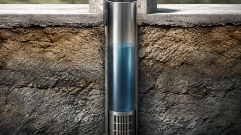
In areas with significant wave action or turbulence (such as a coastal intake station), level sensors should be installed within a stilling well. A stilling well is a vertical pipe that dampens surface fluctuations, providing a steady liquid surface for the sensor to track. For radar sensors, the interior of the pipe must be smooth to prevent signal interference.
Mounting and Orientation
Sensors must be mounted perfectly perpendicular to the liquid surface. Even a few degrees of tilt can result in signal loss or reduced accuracy. In coastal areas, mounting brackets should be made of 316L stainless steel or galvanized steel with marine-grade coatings to prevent structural failure over time.
Surge and Lightning Protection
Coastal installations are often isolated and highly exposed to lightning strikes. Instrumentation should include robust surge protection and be integrated into a well-grounded system to prevent electronic failure during storms.
Limitations and Environmental Challenges
While modern instrumentation is highly advanced, certain coastal conditions pose persistent challenges:
1. Saline Crystallization: Salt spray can dry on the face of an ultrasonic transducer or radar antenna. While radar is more tolerant, a heavy crust of salt can eventually attenuate the signal. Regular inspection and cleaning with fresh water are recommended.
2. Foam and Turbulence: High-velocity discharge or wind-driven chop creates foam. Foam absorbs ultrasonic waves and can scatter radar signals. Selecting a high-power FMCW radar is the best mitigation strategy for foamy surfaces.
3. Tidal Interference: In coastal outfalls, backwater from rising tides can flood flumes, rendering standard level-to-flow calculations invalid. In these cases, redundant sensors (one upstream, one downstream) or area-velocity flow meters are required.
Maintenance and Calibration Protocols
To ensure the longevity of coastal flow liquid measurement systems, a proactive maintenance schedule is necessary.
* Visual Inspections: Check for signs of crevice corrosion on mounting hardware and cable entries.
* Zero-Point Verification: Periodically verify the sensor's zero-point against a physical reference (like a staff gauge) to account for any physical shifting of the mounting structure due to coastal erosion or thermal expansion.
* Signal Strength Monitoring: Modern digital transmitters allow operators to monitor "echo strength." A gradual decline in signal strength often indicates salt buildup on the sensor face before a total failure occurs.
Frequently Asked Questions (FAQ)
Q: Can I use standard 304 stainless steel for coastal flow sensors?
A: No. 304 stainless steel will rapidly corrode in salt-laden environments. 316L is the minimum requirement, and for submerged parts, Titanium or specialized polymers are preferred.
Q: How does salinity affect hydrostatic flow measurement?
A: Hydrostatic sensors measure pressure. Because seawater is denser than freshwater, a sensor calibrated for freshwater will report a level that is approximately 2.5% higher than the actual level in seawater. The transmitter must be programmed with the correct fluid density.
Q: Is radar better than ultrasonic for outdoor coastal channels?
A: Generally, yes. Radar is not affected by wind or the temperature layers that often form over water in coastal areas, making it significantly more reliable for outdoor use.
Q: What IP rating is required for coastal sensors?
A: Instruments should have a minimum rating of IP67. For areas subject to temporary submersion or heavy wave wash-down, IP68 is required.
Conclusion
Coastal flow liquid measurement demands a rigorous selection process that prioritizes environmental resilience alongside measurement precision. By understanding the hydraulic principles of the application and the limitations of different sensing technologies, engineers can implement solutions that withstand the rigors of the marine environment. For those seeking specific product configurations or technical support for complex coastal installations, reviewing the resources on the Main Page provides a foundation for selecting the appropriate radar, ultrasonic, or hydrostatic instrumentation tailored to industrial needs.