What Is a Thermal Well
What Is a Thermal Well
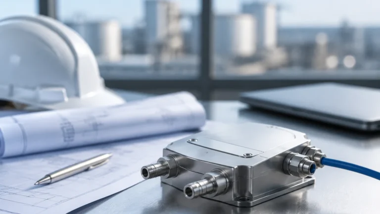
In industrial process control, protecting sensitive instrumentation from the harsh realities of the production environment is a fundamental engineering requirement. A thermal well, more commonly referred to in the industry as a thermowell, is a pressure-tight cylindrical fitting used to protect temperature sensors—such as thermocouples, RTDs (Resistance Temperature Detectors), and bimetal thermometers—from the process media.
By acting as a protective barrier, a thermal well ensures that the sensor is not exposed to high pressures, corrosive chemicals, or high-velocity flows that could lead to mechanical failure or measurement drift. Furthermore, it allows for the removal and replacement of a sensor without requiring a system shutdown or the draining of a vessel, which is critical for maintaining uptime in chemical, oil and gas, and water treatment applications. For engineers designing comprehensive monitoring systems, understanding the nuances of thermal wells is as essential as selecting the right Main Page instrumentation for level and pressure.
Measurement Principles and Functionality
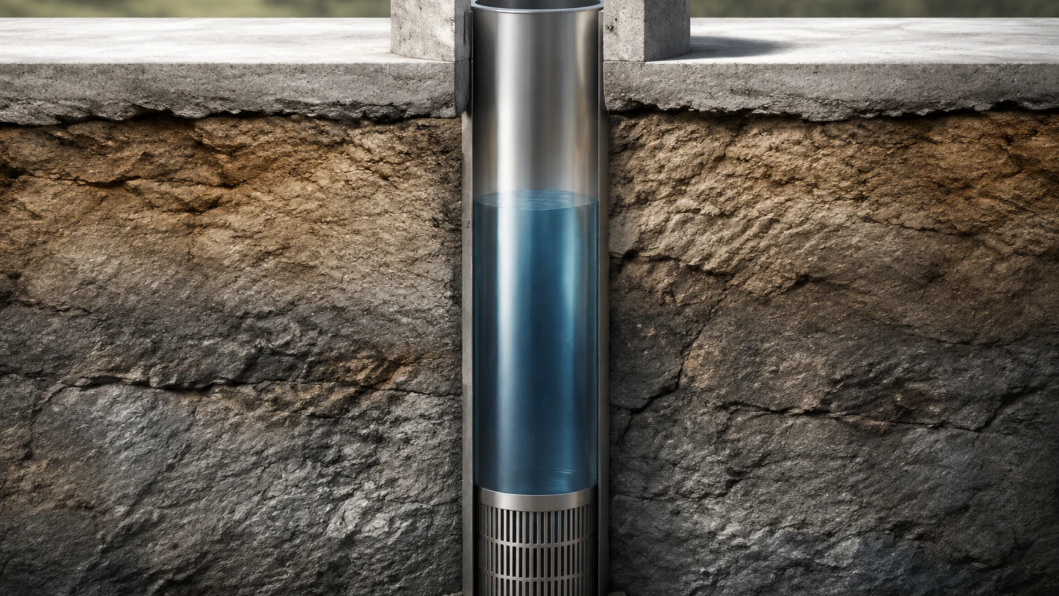
The primary principle behind a thermal well is thermal conduction. The well is installed directly into the process piping or vessel, and the temperature sensor is inserted into the dry internal bore of the well. Heat from the process fluid is transferred through the wall of the thermal well to the sensor via conduction.
Heat Transfer and Thermal Lag
While a thermal well provides essential protection, it introduces a physical barrier that affects the speed of the measurement. This is known as thermal lag. The thickness of the well wall and the material's thermal conductivity determine how quickly the sensor inside can react to changes in the process temperature. To minimize this lag, the internal bore of the thermal well is designed to have a tight fit with the sensor, often utilizing heat-conductive paste or spring-loaded sensors to ensure positive contact with the bottom of the well.
Pressure and Flow Integrity
A thermal well is a pressure-containing component. It must be designed to withstand the full operating pressure of the system. In high-flow environments, the well is also subject to transverse and axial forces. The design must ensure that the "wake frequency" (the frequency of vortices shed as fluid flows past the well) does not coincide with the natural frequency of the thermal well, which could lead to catastrophic vibration failure.
Types of Thermal Wells
Thermal wells are categorized primarily by their connection type to the process and their stem profile. Choosing the correct type depends on the pressure rating, the need for frequent cleaning, and the method of piping installation.
Connection Types
| Connection Type | Description | Best For |
| :— | :— | :— |
| Threaded | Screwed into a threaded pipe fitting or NPT bung. | Low pressure, non-corrosive, small-diameter pipes. |
| Flanged | Bolted to a mating flange on the process vessel or pipe. | High pressure, high temperature, and highly corrosive environments. |
| Socket Weld | Welded into a socket coupling. | Permanent installations where leakage must be zero; high-pressure steam. |
| Weld-In | Welded directly into the process wall or pipe. | Maximum pressure integrity; applications where flanges are not feasible. |
Stem Profiles
1. Straight Stem: The diameter is uniform throughout the immersion length. These are easy to manufacture but have lower natural frequencies, making them less suitable for high-velocity flows.
2. Stepped Stem: The diameter is reduced at the tip (e.g., from 19 mm to 12.5 mm). This reduces the thermal mass at the sensing point, significantly improving response time while maintaining strength at the base.
3. Tapered Stem: The diameter gradually decreases from the base to the tip. This design offers the best strength-to-weight ratio and is the standard for high-velocity applications because it provides a high natural frequency to resist vibration.
Material Selection Criteria
The material of the thermal well must be compatible with the process fluid to prevent corrosion and erosion. Common materials used in industrial automation and chemical processing include:
* Stainless Steel (304/316): The industry standard for water treatment and general chemical applications. It offers good corrosion resistance and high-temperature capability.
* Hastelloy C-276: Used for highly aggressive acids and chlorides where stainless steel would fail.
* Monel 400: Excellent for seawater and hydrofluoric acid applications.
* Inconel 600/625: Preferred for extremely high-temperature applications, such as furnace exhausts or heat treatment processes.
When selecting a material, engineers must also consider the "Velocity Rating." As fluid speed increases, the physical stress on the well increases. Standard tables provided by manufacturers like Welk help determine if a specific material and stem profile can survive the calculated flow forces.
Installation Considerations and Best Practices
Proper installation is critical to ensure both the accuracy of the temperature reading and the mechanical integrity of the system.
Immersion Length
The immersion length (the distance from the tip of the well to the underside of the thread or flange) must be sufficient to ensure the sensing element is fully submerged in the process flow.
* For Liquids: The immersion length should be at least 8 to 10 times the outside diameter of the well.
* For Gases: The immersion length should be 10 to 15 times the outside diameter to account for the lower heat transfer coefficient of gases.
Orientation
In small-diameter pipes (less than 100 mm or 4 in), the thermal well should be installed at an angle or in a pipe elbow. This ensures the tip is pointed upstream, allowing the fluid to flow directly against the sensing area, which improves response time and reduces the risk of stagnant pockets affecting the reading.
Wake Frequency Calculations (ASME PTC 19.3 TW)
For any high-velocity application, a wake frequency calculation according to ASME PTC 19.3 TW is mandatory. This calculation considers the fluid density, velocity, pressure, and temperature, along with the thermal well's dimensions and material properties. If the calculation shows a risk of resonance, the engineer must either shorten the immersion length, increase the root diameter, or use a velocity collar (though collars are generally discouraged in modern piping design due to fitment issues).
Limitations and Risks
While thermal wells are indispensable, they are not without limitations:
* Response Delay: In fast-moving processes where temperature changes occur in milliseconds, the thermal mass of a heavy-duty well may be too slow. In these rare cases, a bare sensor with a specialized coating might be required, though this sacrifices sensor longevity.
* Cleaning Requirements: In the food and beverage or pharmaceutical industries, thermal wells must be "sanitary" (e.g., Tri-Clamp connections) to prevent bacterial growth in crevices. Standard threaded wells are prohibited in these sectors.
* Vibration Failure: As mentioned, if the fluid velocity creates vortices at a frequency matching the well's natural frequency, the well can snap off, potentially damaging downstream equipment like pumps or turbines.
Frequently Asked Questions (FAQs)
Q: Can I use a thermal well for level measurement?
A: No, a thermal well is strictly for temperature sensors. However, temperature compensation is often required for accurate level measurement in hydrostatic or radar systems. For integrated solutions, you can visit the Main Page of our instrumentation catalog.
Q: How do I know if my thermal well is failing?
A: Signs of failure include erratic temperature readings (indicating a cracked well allowing fluid to touch the sensor), physical bending of the stem during inspection, or visible pitting/corrosion on the surface.
Q: What is the difference between "U" length and "T" length?
A: "U" length is the immersion length (the portion inside the process). "T" length is the lagging extension, which is the portion of the well that extends outside the pipe to allow for insulation thickness.
Q: Should I use a tapered or straight well?
A: A tapered well is generally superior for high-flow applications due to its higher natural frequency. A straight well is typically sufficient for low-velocity tanks or large-volume storage vessels.
Summary for Project Planning
Before finalizing a thermal well specification, project managers and engineers should confirm the following data points:
1. Process Fluid Velocity: Maximum and normal operating flow rates.
2. Fluid Properties: Density, viscosity, and chemical composition.
3. Operating Pressure and Temperature: Including potential surge conditions.
4. Pipe Size: To determine the appropriate immersion length and connection type.
By carefully evaluating these factors, you ensure that the temperature monitoring system remains accurate and safe throughout its service life. For more information on how temperature monitoring integrates with industrial level and flow control, explore the technical resources available at https://www.level-meters.com/.