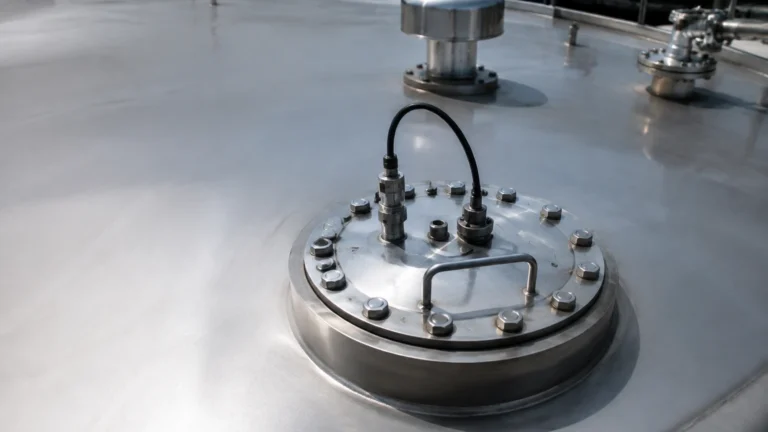
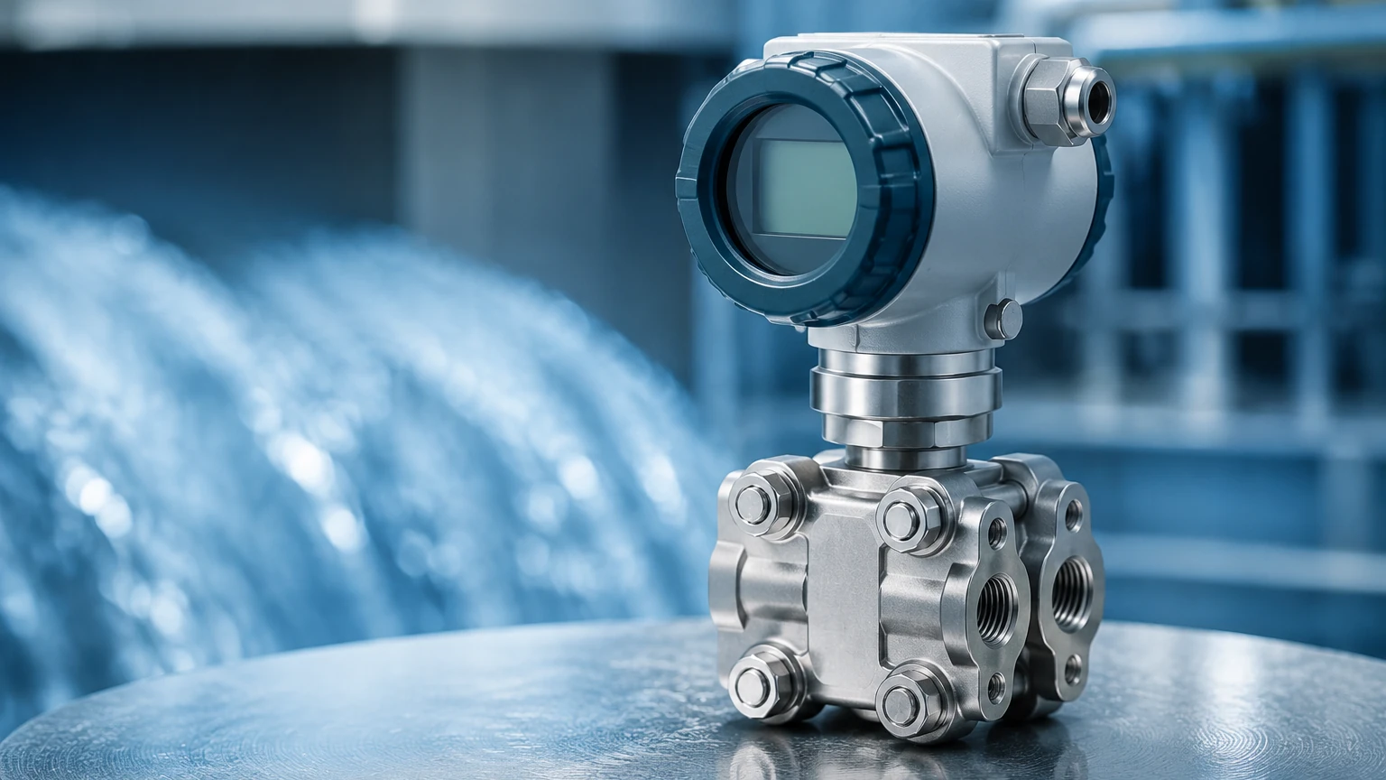
Compound Pressure Sensor
Compound Pressure Sensor
In the field of industrial instrumentation, precision is the cornerstone of safety and efficiency. Among the various devices used to monitor process conditions, the compound pressure sensor stands out for its unique ability to measure a continuous range of pressure that spans both vacuum and positive gauge pressure. Unlike standard gauge sensors that only measure above atmospheric pressure, or vacuum sensors that only measure below it, a compound pressure sensor provides a seamless transition across the atmospheric zero point.
For engineers and technicians working in sectors such as water treatment, chemical processing, and industrial automation, understanding the nuances of these instruments is essential. This guide explores the measurement principles, selection criteria, and practical applications of compound pressure sensors within modern industrial frameworks.
Measurement Principles and Technology
To understand a compound pressure sensor, one must first distinguish between the three primary types of pressure measurement: absolute, gauge, and vacuum.
1. Absolute Pressure: Measured relative to a perfect vacuum.
2. Gauge Pressure: Measured relative to the current atmospheric pressure.
3. Vacuum Pressure: Measured as the decrease below atmospheric pressure.
A compound pressure sensor is essentially a specialized gauge pressure transmitter. It uses the ambient atmospheric pressure as its reference (zero) point. However, the sensing element—typically a diaphragm—is engineered to deflect in two directions. When the process pressure is lower than the atmospheric pressure, the diaphragm moves in one direction (indicating vacuum); when the process pressure exceeds atmospheric pressure, it moves in the opposite direction (indicating positive pressure).
Sensing Technologies
Most industrial compound pressure sensors utilize one of three primary sensing technologies:
* Piezoresistive Strain Gauges: These sensors use a silicon or metal diaphragm with integrated resistors. As the diaphragm flexes under pressure or vacuum, the electrical resistance changes. This change is proportional to the applied pressure and is converted into an electrical signal.
* Ceramic Capacitive Sensors: These feature a ceramic diaphragm that forms one plate of a capacitor. Pressure changes the distance between the ceramic plate and a substrate, altering the capacitance. These are highly resistant to corrosion and mechanical wear.
* Thin-Film Sensors: Created by sputtering metal or ceramic onto a stainless steel diaphragm, these sensors offer excellent long-term stability and are often used in high-pressure or high-vibration environments.
By integrating these technologies, manufacturers like Welk produce instruments capable of maintaining high accuracy across a wide dynamic range, often spanning from -1 bar (-100 kPa) to 10 bar (1 MPa) or higher.
Key Evaluation and Selection Criteria
Selecting the right compound pressure sensor requires more than just knowing the pressure range. Engineers must evaluate the instrument based on the specific demands of the process environment. For a comprehensive look at available measurement technologies, professionals often visit the Main Page of specialized manufacturers to compare technical specifications.
1. Pressure Range and Overpressure Limits
Compound sensors are defined by their span, such as -1 to +5 bar. It is critical to ensure that the sensor can handle the maximum expected positive pressure without damage. The "overpressure rating" (typically 1.5x to 3x the full scale) defines the limit the sensor can withstand before losing its calibration or suffering mechanical failure.
2. Media Compatibility (Wetted Materials)
The "wetted parts" are the components of the sensor that come into direct contact with the process fluid. For water treatment, 316L stainless steel is often sufficient. However, in chemical processing involving acids or chlorides, materials like Hastelloy, Monel, or ceramic diaphragms may be required to prevent corrosion.
3. Output Signals and Integration
Industrial automation systems rely on standardized signals. Common options include:
* 4-20 mA Current Loop: The industry standard for long-distance transmission, as it is resistant to electrical noise.
* 0-10 VDC: Common in HVAC and laboratory settings.
* Digital Protocols (RS485/Modbus): Allows for the transmission of multiple variables, including temperature and diagnostic data, over a single pair of wires.
4. Accuracy and Thermal Drift
Accuracy is usually expressed as a percentage of the Full Scale (FS). A typical industrial compound pressure sensor might offer ±0.25% or ±0.5% FS accuracy. Because pressure sensors are sensitive to temperature changes, the "thermal error band" or "compensated temperature range" must be checked to ensure the device remains accurate in outdoor or high-heat applications.
| Feature | Standard Industrial Specification | High-Precision Specification |
| :— | :— | :— |
| Pressure Range | -1 to 10 bar | -1 to 2 bar |
| Accuracy | ±0.5% FS | ±0.1% FS |
| Wetted Material | 316L Stainless Steel | Hastelloy C-276 / Ceramic |
| Output | 4-20 mA | Modbus RTU / HART |
| Operating Temp | -20°C to +80°C | -40°C to +125°C |
Practical Applications in Industry
The versatility of the compound pressure sensor makes it indispensable in several specific scenarios where the process might fluctuate between vacuum and positive states.
Pump Suction and Discharge Monitoring
In many pumping systems, the suction side may experience a vacuum if the supply tank is low or if there is a restriction in the inlet line. Conversely, during normal operation or priming, the same point might experience positive pressure. A compound sensor allows a single instrument to monitor both conditions, protecting the pump from cavitation and dry-running.
Sealed Tank Level Measurement
In pressurized or vacuum-sealed tanks, level measurement using hydrostatic pressure requires compensation for the "head space" pressure. A compound pressure sensor is used to measure the gas pressure above the liquid. If the tank is purged with nitrogen (positive pressure) but also subjected to vacuum during cleaning or filling, a compound sensor is the only way to accurately track the headspace conditions.
Leak Detection and Vacuum Packaging
In systems where a vacuum is pulled and then held, such as in refrigeration charging or food packaging, the sensor must monitor the pull-down to a deep vacuum and then detect any rise toward atmospheric pressure (or even positive pressure if a leak occurs in a pressurized environment).
Vapor Recovery Systems
In oil and gas applications, vapor recovery units (VRUs) often operate at very low pressures. The system may fluctuate between a slight vacuum (pulling vapors) and a slight positive pressure (during storage or transfer). Compound sensors provide the resolution needed for these narrow, sensitive ranges.
Installation Considerations and Best Practices
Proper installation is as important as selecting the correct sensor. Failure to follow engineering best practices can lead to premature sensor failure or inaccurate readings.
1. Orientation and Mounting: While most sensors can be mounted in any orientation, they are often calibrated in a vertical position. Mounting a sensor horizontally or upside down may cause a small "zero shift" due to the weight of the internal fluid or the diaphragm itself. This should be accounted for during commissioning.
2. Venting for Gauge Reference: Since a compound pressure sensor is referenced to the atmosphere, it must have a way to "breathe." This is usually achieved through a small vent hole in the connector or a vented cable. It is vital to ensure this vent is not blocked by paint, dust, or moisture.
3. Pressure Snubbers and Syphons: In applications with rapid pressure spikes (water hammer) or high-temperature steam, accessories like snubbers or pigtail syphons should be used. A snubber dampens pressure surges that could rupture the diaphragm, while a syphon allows steam to condense into a water seal, protecting the sensor from extreme heat.
4. Electrical Grounding: To prevent electromagnetic interference (EMI) from affecting the signal, the sensor housing should be properly grounded, and shielded cabling should be used, especially in environments with large motors or variable frequency drives (VFDs).
Limitations and Common Risks
Despite their utility, compound pressure sensors have limitations that engineers must recognize:
* Resolution Constraints: If a sensor is designed for a very wide positive range (e.g., -1 to 50 bar), the resolution in the vacuum range (-1 to 0 bar) will be relatively poor. For applications requiring high-precision vacuum measurement alongside high positive pressure, two separate sensors may be more effective.
* Condensation in Vent Tubes: In humid environments, moisture can condense inside the atmospheric reference tube. This can create a "water column" that offsets the zero point or, in extreme cases, damages the internal electronics. Using a desiccated vent filter can mitigate this risk.
* Diaphragm Fatigue: In applications with high-cycle pressure fluctuations (e.g., rapid reciprocating pumps), the diaphragm may eventually suffer from metal fatigue. In these cases, choosing a sensor with a higher overpressure rating or a thicker diaphragm material is advisable.
Frequently Asked Questions (FAQ)
Q: Can I use a standard gauge pressure sensor to measure vacuum?
A: Generally, no. Standard gauge sensors are designed to measure pressure in one direction. Attempting to apply a vacuum to a sensor not rated for it may pull the diaphragm against the internal sensor housing, causing permanent damage or calibration shift.
Q: How do I calibrate a compound pressure sensor?
A: Calibration requires a dual-source pressure pump capable of generating both vacuum and positive pressure. The technician typically checks the "zero" at atmospheric pressure, the "span" at maximum positive pressure, and a "downscale" point at the maximum vacuum level.
Q: What is the difference between a compound sensor and a vacuum sensor?
A: A vacuum sensor only measures the range from -1 bar to 0 bar (atmospheric). It cannot measure positive pressure. A compound sensor measures both, typically from -1 bar up to a specified positive limit (e.g., +5, +10, or +20 bar).
Q: Are compound sensors suitable for hygienic applications?
A: Yes, provided they are equipped with a flush diaphragm and a sanitary connection (like a Tri-Clamp). These are commonly used in the food and beverage industry for tanks that undergo both vacuum cleaning and pressurized filling.
Conclusion
The compound pressure sensor is a versatile and robust tool in the industrial engineer's arsenal. By bridging the gap between vacuum and positive pressure, it simplifies system design and reduces the number of required process penetrations. When selecting a sensor, it is crucial to confirm the chemical compatibility of the wetted materials, the electrical requirements of the control system, and the physical constraints of the installation site. For those seeking reliable, accurate, and cost-effective level and pressure measurement solutions, consulting with a professional manufacturer and reviewing technical data on their Main Page is the recommended next step to ensuring process integrity.