3000 Electromagnetic Flow Meter
3000 Electromagnetic Flow Meter
In the realm of industrial process control, the accurate measurement of liquid flow is as critical as monitoring tank levels. The 3000 electromagnetic flow meter represents a high-performance solution designed for the volumetric flow measurement of conductive liquids. Often utilized in tandem with advanced level sensors, these instruments provide the data necessary for mass balance, chemical dosing, and custody transfer in sectors ranging from wastewater treatment to heavy chemical processing.
Understanding the technical nuances of the 3000 electromagnetic flow meter is essential for engineers tasked with optimizing plant efficiency. This guide details the measurement principles, selection criteria, and installation protocols required to ensure long-term reliability and accuracy in demanding industrial environments.
Measurement Principle: Faraday’s Law of Induction
The operation of the 3000 electromagnetic flow meter is based on Faraday’s Law of Electromagnetic Induction. This principle states that a conductor moving through a magnetic field generates an electromotive force (voltage) proportional to its velocity. In the context of a flow meter, the "conductor" is the process liquid itself.
The Mathematical Foundation
The relationship is expressed by the formula:
E = k · B · v · D
Where:
* E is the induced voltage (the signal measured by the electrodes).
* k is a constant specific to the instrument design.
* B is the magnetic field strength generated by the internal coils.
* v is the average velocity of the liquid.
* D is the internal diameter of the measuring pipe (the distance between electrodes).
Because the magnetic field (B) and the pipe diameter (D) are constant, the induced voltage (E) is directly and linearly proportional to the flow velocity (v). This linearity is one of the primary advantages of the 3000 series, as it allows for high accuracy across a wide turndown ratio. For the meter to function, the liquid must have a minimum electrical conductivity, typically ≥ 5 μS/cm (microsiemens per centimeter).
Technical Architecture of the 3000 Series
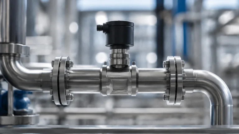
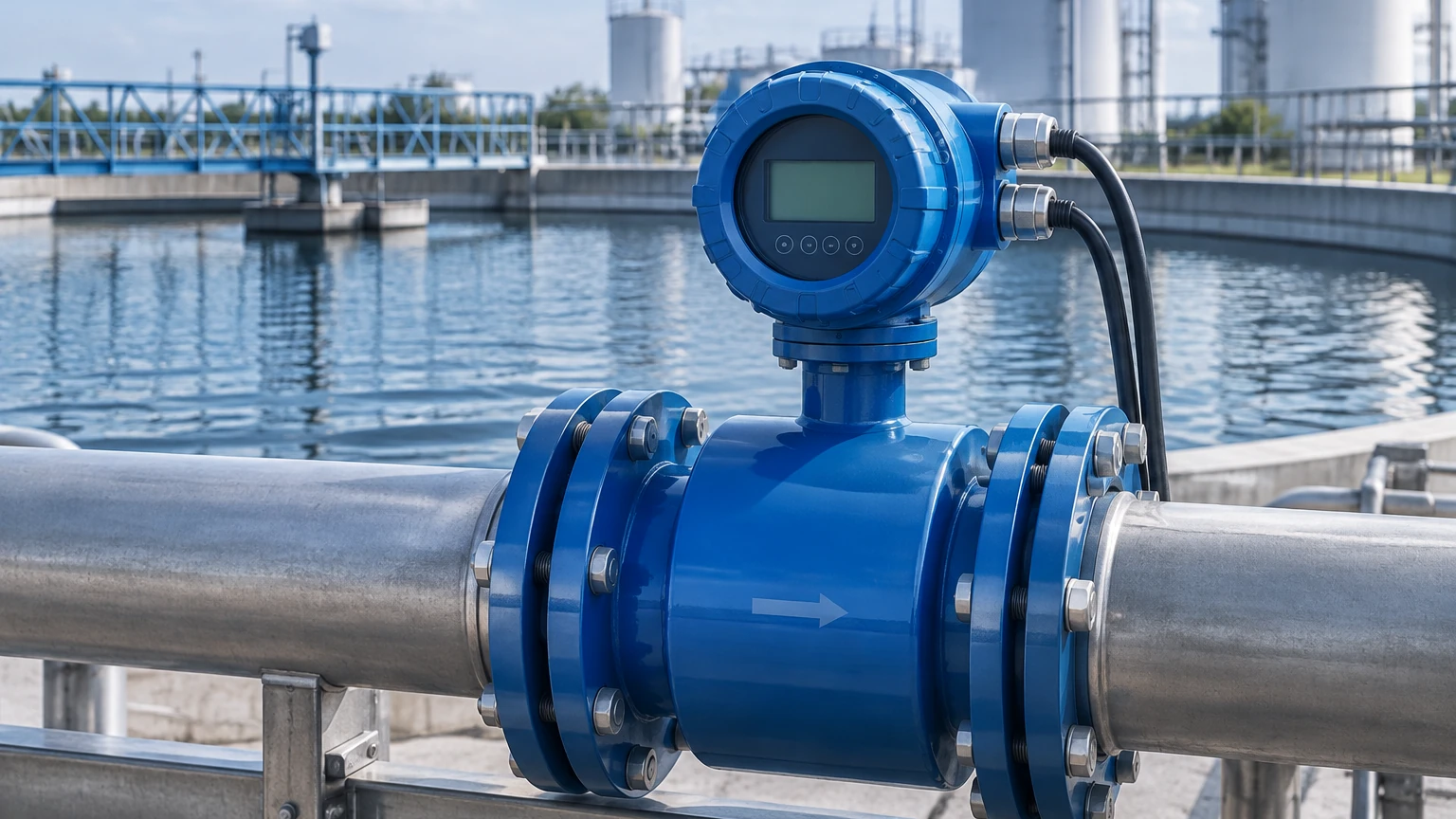
The 3000 electromagnetic flow meter consists of two primary components: the primary sensor (the flow tube) and the signal converter (the 3000 series transmitter). The sensor is installed directly in the pipeline, while the converter can be mounted integrally or remotely.
The Signal Converter
The "3000" designation often refers to the advanced signal converter unit. This component is responsible for driving the excitation coils to create a stable magnetic field and processing the microvolt-level signals captured by the electrodes. Modern 3000 series converters feature digital signal processing (DSP) to filter out electrochemical noise and provide stable readings even in applications with pulsating flows or high solids content.
Material Construction
To withstand diverse industrial fluids, the flow tube is lined with non-conductive, corrosion-resistant materials. The electrodes, which come into direct contact with the media, are manufactured from high-grade alloys. Selecting the correct combination of liner and electrode is the most critical step in the procurement process.
Selection Criteria and Practical Tables
Choosing the right 3000 electromagnetic flow meter requires an analysis of the chemical properties, temperature, and abrasive nature of the fluid. The following tables provide a reference for common material selections.
Table 1: Lining Material Selection
| Lining Material | Temperature Range | Characteristics | Typical Applications |
| :— | :— | :— | :— |
| PTFE (Teflon) | -40°C to +180°C | Exceptional chemical resistance; anti-adhesive properties. | Strong acids, alkalis, and high-temperature chemicals. |
| Hard Rubber | 0°C to +60°C | Good abrasion resistance; cost-effective for large diameters. | Municipal water, wastewater, and cooling water systems. |
| Polyurethane (PU) | -20°C to +60°C | Extremely high abrasion resistance. | Mining slurries, sand-water mixtures, and pulp. |
| PFA | -40°C to +150°C | Similar to PTFE but with better mechanical stability under vacuum. | Pharmaceutical and food-grade processes; vacuum lines. |
Table 2: Electrode Material Selection
| Electrode Material | Corrosion Resistance | Application Context |
| :— | :— | :— |
| Stainless Steel 316L | Moderate | Water, wastewater, and mildly corrosive organic liquids. |
| Hastelloy C | High | Oxidizing salts, hydrochloric acid, and mixed chemical waste. |
| Titanium | High | Seawater, chlorides, and chlorite solutions. |
| Tantalum | Superior | Highly aggressive acids like sulfuric or nitric acid (except HF). |
| Platinum-Iridium | Maximum | Most corrosive media; used where absolute purity is required. |
| Graphite/Carbide | High | Specifically for abrasive slurries where metal electrodes may wear. |
Installation Considerations
To achieve the specified accuracy (typically ±0.5% or better), the 3000 electromagnetic flow meter must be installed according to strict engineering guidelines. The most common cause of measurement error is an asymmetrical flow profile or an incompletely filled pipe.
1. Straight Pipe Requirements
Flow disturbances caused by elbows, valves, or pumps can create turbulence that affects the magnetic field's interaction with the fluid. To ensure a stable flow profile, follow the "5D/3D" rule:
* Upstream: Provide a straight run of at least 5 times the nominal pipe diameter (5D).
* Downstream: Provide a straight run of at least 3 times the nominal pipe diameter (3D).
* If a control valve is used, it should always be installed downstream of the meter to prevent cavitation and air entrainment.
2. Orientation and Filling
The flow meter should ideally be installed in a vertical pipe with the flow moving upward. This orientation ensures that the pipe remains completely full and that any air bubbles rise away from the electrodes. If horizontal installation is necessary, the meter must be placed at a low point in the piping system. The electrodes should be positioned on the horizontal plane (3 o'clock and 9 o'clock positions) to prevent interference from sediment at the bottom or air pockets at the top.
3. Grounding
Since the flow signal is a very low voltage, electrical noise can easily interfere with the measurement. The liquid, the sensor, and the converter must be at the same electrical potential. In metal piping, this is usually achieved by bonding the sensor flanges to the pipe flanges. In plastic or lined piping, grounding rings must be installed between the sensor and the pipe to provide a path to the fluid.
Operational Limitations
While the 3000 electromagnetic flow meter is highly versatile, it is not suitable for all applications. Engineers should be aware of the following limitations:
* Non-Conductive Liquids: These meters cannot measure hydrocarbons (oils, fuels), distilled water, or gases. If the conductivity drops below the threshold, the signal will be lost.
* Vacuum Conditions: Certain liners, particularly PTFE, can collapse or peel away from the flow tube under vacuum conditions. PFA or specially reinforced liners should be specified if a vacuum is possible.
* Coating and Scaling: If the process fluid tends to leave deposits (e.g., calcium buildup or oily films), the electrodes may become insulated, leading to measurement drift or failure. Regular cleaning or the use of ultrasonic electrode cleaning modules may be required.
Integration with Industrial Systems
In modern industrial automation, flow measurement is rarely an isolated data point. For instance, in chemical storage and distribution, the flow rate provided by the 3000 series is often cross-referenced with level data from radar or ultrasonic sensors to ensure inventory accuracy.
As a professional manufacturer of industrial instrumentation, Welk provides a comprehensive range of measurement solutions that work in harmony with flow systems. For engineers looking to integrate high-precision monitoring across their entire facility, reviewing the options on the Main Page can provide insights into how radar level meters and magnetic gauges complement flow data for total process transparency.
Frequently Asked Questions (FAQ)
Q: Can the 3000 electromagnetic flow meter measure steam?
A: No. Electromagnetic flow meters only work with conductive liquids. Steam is a gas and does not possess the necessary electrical conductivity. For steam measurement, vortex or differential pressure flow meters are typically used.
Q: What happens if the pipe is only partially full?
A: The meter will provide an inaccurate reading, usually higher or lower than the actual flow depending on the electrode position. Most 3000 series converters include an "Empty Pipe Alarm" to alert operators when the fluid level drops below the electrodes.
Q: How often does the meter need to be calibrated?
A: Because there are no moving parts to wear out, the 3000 series is extremely stable. In many water applications, calibration is only required every 2 to 5 years. However, in corrosive or abrasive chemical applications, annual verification is recommended to ensure electrode integrity.
Q: Can it handle bidirectional flow?
A: Yes, the 3000 electromagnetic flow meter is inherently bidirectional. The converter can be configured to show forward flow, reverse flow, and a net totalizer, which is particularly useful in water distribution networks and pumping stations.
Q: Is there a minimum velocity requirement?
A: While the meter can detect very low flows, accuracy typically degrades below 0.3 m/s. For optimal performance, the pipe size should be selected so that the average velocity during normal operation falls between 1 m/s and 3 m/s.
By adhering to these principles and selection guidelines, industrial operators can leverage the 3000 electromagnetic flow meter to achieve precise, maintenance-free flow monitoring that stands the test of time in the most challenging process environments.