Conductance Level Sensor
Conductance Level Sensor
In the landscape of industrial automation and process control, the conductance level sensor remains one of the most reliable and cost-effective solutions for point-level detection in conductive liquids. Often referred to as a conductivity switch or electrode level sensor, this technology leverages the electrical properties of the process medium to trigger alarms, control pumps, or manage inventory. For engineers and facility managers, understanding the nuances of conductance technology is essential for ensuring system longevity and operational safety.
Understanding Conductance Level Measurement Principles
The fundamental principle behind a conductance level sensor is the completion of an electrical circuit. Unlike continuous level measurement technologies like radar or ultrasonic sensors, conductance sensors are typically used for point-level detection—identifying when a liquid reaches a specific height (High, Low, or Intermediate levels).
The Electrical Circuit
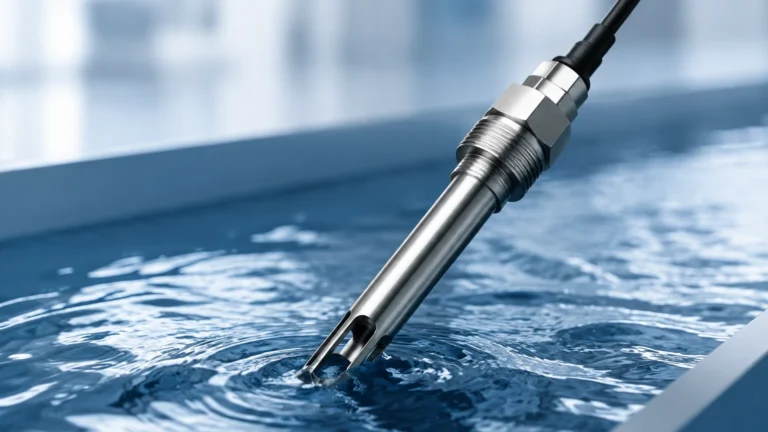
At its core, the system consists of a low-voltage power source (usually integrated into a controller or relay), a reference electrode (or the conductive tank wall), and one or more measuring electrodes. When the liquid level rises and touches a measuring electrode, the liquid acts as a conductor, allowing a small electrical current to flow from the electrode through the liquid to the reference electrode.
AC vs. DC Current
High-quality conductance level sensors utilize a low-voltage Alternating Current (AC) rather than Direct Current (DC). The use of AC is critical for two reasons:
1. Prevention of Electrolysis: DC current can cause the decomposition of the liquid and the buildup of ions on the probes, leading to rapid corrosion and sensor failure.
2. Polarization Mitigation: AC prevents the polarization of the electrodes, which would otherwise increase electrical resistance and lead to false readings.
The controller monitors the resistance (or its reciprocal, conductance) between the probes. When the resistance drops below a pre-set threshold (indicating liquid presence), the output relay changes state. Sensitivity adjustments on the controller allow the system to be tuned for liquids with varying levels of conductivity, from highly conductive acids to moderately conductive tap water.
Key Components of a Conductance Level System
A complete conductance level sensing installation typically involves three primary elements:
1. The Electrodes (Probes): These are the sensing elements that enter the tank. They are available as rigid rods for shorter depths or flexible cables for deep wells and large reservoirs. Materials typically include 316 Stainless Steel, Hastelloy, or Titanium, depending on the chemical aggressiveness of the medium.
2. The Probe Head (Housing): This component mounts to the tank process connection (threaded or flanged) and provides the electrical terminals for wiring. It must offer appropriate Ingress Protection (IP) ratings, such as IP65 or IP67, to withstand industrial environments.
3. The Controller/Relay: This is the "brain" of the system, usually mounted in a remote control panel or on a DIN rail. It provides the excitation voltage to the probes and processes the return signal to trigger a switch output (SPDT or DPDT).
Industrial Applications and Use Cases
Conductance level sensors are ubiquitous in industries where conductive liquids are processed. Their simplicity makes them the preferred choice for "fail-safe" applications.
* Water and Wastewater Treatment: Monitoring levels in sumps, wet wells, and storage tanks. They are frequently used to prevent pump dry-running or to manage tank filling cycles (pump-up/pump-down logic).
* Food and Beverage: Detecting levels in beer, milk, or fruit juices. In these applications, hygienic probe designs with polished surfaces and food-grade insulation (like PTFE) are required.
* Chemical Processing: Managing acidic or alkaline solutions. Because the probes can be coated in specialized materials like PFA or ETFE, they can withstand highly corrosive environments.
* Boiler Feedwater: Detecting high and low water levels in steam boilers. Specialized high-pressure and high-temperature conductance probes are used to ensure boiler safety.
Selection Criteria and Technical Specifications
Choosing the right conductance level sensor requires an evaluation of both the liquid properties and the physical environment. The following table provides a general guideline for selecting probe and insulation materials based on application needs.
Selection Table: Material Compatibility
| Application | Recommended Probe Material | Insulation Material | Typical Conductivity (µS/cm) |
| :— | :— | :— | :— |
| Potable Water | 316 Stainless Steel | PVC / Polypropylene | 50 – 1,000 |
| Wastewater / Sewage | 316 Stainless Steel | Heat-shrink Polyolefin | 500 – 5,000 |
| Strong Acids (HCl, H2SO4) | Hastelloy C / Titanium | PTFE / PFA | > 10,000 |
| Food & Dairy | 316L Stainless Steel | PTFE (Food Grade) | 200 – 4,000 |
| Condensate / Distilled Water | 316 Stainless Steel | PTFE | 0.5 – 50 |
Conductivity Thresholds
It is vital to confirm that the liquid's conductivity exceeds the minimum sensitivity of the controller. Most industrial controllers can detect liquids with a conductivity as low as 1 µS/cm (microsiemens per centimeter), though standard tap water is usually around 50–800 µS/cm. If the liquid is non-conductive (like oils, hydrocarbons, or pure deionized water), a conductance level sensor will not function, and alternative technologies like ultrasonic or radar level meters should be considered.
Installation and Mounting Best Practices
Proper installation is paramount to preventing false triggers and ensuring the long-term reliability of the conductance level sensor.
* Reference Grounding: In metal tanks, the tank wall itself can often act as the reference (ground) electrode. However, in plastic or fiberglass (FRP) tanks, a dedicated reference electrode must be installed. This reference probe should be the longest probe in the assembly, reaching below the lowest control point.
* Probe Spacing: Ensure that probes are spaced far enough apart to prevent "bridging." Bridging occurs when moisture, foam, or debris creates a conductive path between two electrodes even when the liquid level is low. A minimum spacing of 20 mm (approx. 0.8 inches) is generally recommended.
* Vertical vs. Horizontal Mounting: While most conductance probes are mounted vertically from the top of the tank, some single-point probes can be mounted horizontally through the side wall. For vertical mounts, ensure the probes do not swing into contact with the tank wall or each other due to turbulence.
* Turbulence and Stillwells: In tanks with heavy agitation or splashing, probes should be installed inside a stillwell (a perforated pipe) to prevent the liquid's surface movement from causing "chatter" in the relay output.
* Wiring Precautions: Use shielded cable for long runs between the probe head and the controller to prevent electromagnetic interference (EMI) from inducing a false signal in the high-sensitivity circuit.

Limitations and Operational Challenges
While highly effective, the conductance level sensor has specific limitations that engineers must account for during the design phase:
1. Coating and Scaling: If the liquid leaves a conductive residue or scale (such as calcium deposits or thick sludge) on the insulation, it can create a permanent conductive path between the probe and the ground. This results in a "false high" reading. Periodic cleaning or the use of "anti-fouling" probe designs is necessary in these environments.
2. Foam Interference: Conductive foam can trigger the sensor just as effectively as the liquid itself. If foam detection is not desired, the sensitivity of the controller must be turned down, or a different technology (like a displacement switch) may be required.
3. Non-Conductive Liquids: As mentioned, this technology is fundamentally incompatible with hydrocarbons, oils, and highly purified waters. Always verify the conductivity of the medium at the expected process temperature, as conductivity often increases with temperature.
4. Pressure and Temperature Limits: Standard industrial probes are often rated up to 10 bar (145 psi) and 100°C (212°F). High-pressure steam applications require specialized ceramic-to-metal seals and heavy-duty electrodes.
Comparison with Alternative Level Technologies
When evaluating point-level solutions, it is helpful to compare the conductance level sensor against other common technologies.
| Feature | Conductance Sensor | Float Switch | Ultrasonic (Point) | Tuning Fork (Vibrating) |
| :— | :— | :— | :— | :— |
| Moving Parts | None | Yes | None | Minimal (Vibration) |
| Cost | Low | Low to Medium | Medium | Medium to High |
| Liquid Type | Conductive only | Any (Density dependent) | Any | Any (Viscosity limits) |
| Maintenance | Low (unless scaling) | Moderate (mechanical wear) | Low | Low |
| Setup | Simple | Simple | Moderate | Simple |
For many standard water-based applications, the lack of moving parts makes the conductance sensor superior to mechanical float switches, which are prone to jamming or leaking over time.
Frequently Asked Questions (FAQs)
Q: Can I cut the electrode rods to length on-site?
A: Yes, most rigid rod electrodes are designed to be cut to the desired length during installation. However, ensure that you do not damage the insulation (if present) and that you recalibrate the controller sensitivity if the rod length is significantly altered.
Q: How do I test if my conductance sensor is working?
A: You can perform a manual bridge test. With the controller powered on, use a jumper wire to momentarily connect the measuring probe terminal to the reference probe terminal. The relay should click and the indicator LED should change state. If the sensor is in the tank, you can use a bucket of the process liquid to submerge the probes manually.
Q: What causes the relay to "chatter" (rapidly switch on and off)?
A: Chattering is usually caused by surface turbulence or waves in the tank. Most modern conductance controllers include a built-in time delay (e.g., 0.5 to 3 seconds) that can be adjusted to ignore momentary contact caused by splashing.
Q: Is it safe to use these sensors in flammable liquids?
A: Only if the system is used in conjunction with an intrinsically safe (IS) barrier. The barrier limits the energy sent to the probes in the hazardous area to levels that cannot ignite an explosive atmosphere. Always check for ATEX or IECEx certification for such applications.
Conclusion
The conductance level sensor remains a cornerstone of industrial level control due to its durability, simplicity, and low cost of ownership. By correctly matching probe materials to the chemical environment and ensuring proper installation away from turbulence and potential bridging, users can achieve years of maintenance-free operation. For projects requiring a broader range of measurement solutions, including continuous monitoring or non-contact sensing, engineers are encouraged to Review product options and application support to find the most appropriate instrument for their specific process requirements.