Conductivity Controls
Conductivity Controls
In the landscape of industrial automation and process management, maintaining precise liquid levels is a fundamental requirement for safety, efficiency, and product quality. Among the various technologies available, conductivity controls represent one of the most robust, cost-effective, and widely utilized methods for point-level detection in conductive liquids. These systems, often referred to as conductive level switches or probes, leverage the electrical properties of the process medium to trigger alarms, manage pumps, and control valves.
For engineers and plant managers, understanding the nuances of conductivity controls is essential for selecting the right instrumentation for applications ranging from simple water storage to complex chemical processing. This guide provides a technical overview of the principles, selection criteria, and installation requirements for these essential industrial tools.
Understanding the Principle of Conductive Level Measurement
Conductivity level measurement is based on a simple physical principle: the ability of a liquid to conduct an electrical current. The system typically consists of one or more metallic electrodes (probes) and a control unit (relay).
The Electrical Circuit
When the liquid level rises and makes contact with an electrode, it completes an electrical circuit between the probe and a reference point. This reference point can be the wall of a metallic tank or a dedicated "common" electrode in non-conductive (plastic or concrete) vessels. The control unit applies a low-voltage alternating current (AC) to the probes. When the circuit is closed by the presence of the liquid, the resulting current flow is detected by the controller, which then switches an output relay.
Why AC is Used
It is critical to note that conductivity controls utilize AC voltage rather than direct current (DC). The use of DC would lead to electrolysis, causing the decomposition of the liquid and the rapid corrosion or buildup of material on the electrodes. By using a low-frequency AC signal, the system prevents polarization and ensures long-term stability of the probe surface.
Sensitivity and Conductivity Thresholds
The effectiveness of these controls depends on the conductivity of the medium, measured in Siemens per meter (S/m) or more commonly microsiemens per centimeter (µS/cm). Most industrial controllers feature adjustable sensitivity settings, allowing them to be tuned to the specific conductivity of the liquid. This adjustability is vital for distinguishing between the actual liquid level and environmental factors such as high humidity, foam, or residue buildup on the probe insulators.
Key Components of Conductivity Control Systems
A standard conductivity control setup involves three primary elements: the electrodes, the probe head/housing, and the controller.
1. Electrodes (Probes)
Electrodes are the sensing elements that come into direct contact with the process media. They are typically manufactured from corrosion-resistant materials such as 316 Stainless Steel, though specialized materials like Hastelloy, Titanium, or Monel are used for highly aggressive chemicals.
* Rod Probes: Solid metal rods used for vertical installation. These are durable and suitable for most tank applications.
* Wire/Cable Probes: Used in deep wells or tall silos where rigid rods would be impractical to ship or install. These are weighted to ensure they remain vertical.
2. Probe Head and Housing
The probe head secures the electrodes and provides the electrical connection points. In industrial environments, these housings must meet specific Ingress Protection (IP) ratings, such as IP65 or IP67, to protect against moisture and dust. For hazardous environments, explosion-proof housings are required.
3. The Controller (Relay Unit)
The controller is the "brain" of the system. It is usually mounted remotely in a control panel on a DIN rail. The controller performs several functions:
* Providing the excitation voltage to the probes.
* Monitoring current flow and comparing it against the sensitivity threshold.
* Providing time-delay functions to prevent "chattering" caused by surface turbulence.
* Managing logic for pump control (e.g., start at high level, stop at low level).
Selection Criteria for Industrial Applications
Selecting the appropriate conductivity controls requires a thorough evaluation of the process environment. The following table summarizes key considerations for different application types:
| Feature | Single-Point Detection | Multi-Point Control (e.g., Pump Logic) |
| :— | :— | :— |
| Number of Probes | 2 (1 level + 1 common) | 3 or more (High, Low, and Common) |
| Primary Use | Overfill alarm or run-dry protection | Automatic tank filling or emptying |
| Vessel Type | Metallic or Non-Metallic | Metallic or Non-Metallic |
| Controller Type | Simple Relay | Logic Controller with Hysteresis |
| Typical Medium | Acids, Alkalis, Water | Wastewater, Cooling Tower Water |
Medium Properties
The first question is always: "Is the liquid conductive?" Most water-based liquids, including wastewater, acids, and salt solutions, are excellent candidates. However, pure oils, hydrocarbons, and ultrapure distilled water have very low conductivity and cannot be measured using this technology.
Temperature and Pressure
Standard probes are often rated for temperatures up to 100°C and moderate pressures. However, for high-pressure boiler applications or high-temperature chemical reactors, specialized probes with ceramic or PEEK insulators and high-grade seals are necessary. Standard rod diameters usually range from 4mm to 10mm, depending on the required mechanical strength.
Installation Guidelines and Best Practices
Proper installation is paramount to the reliability of conductivity controls. Failure to follow engineering best practices often leads to false readings or premature equipment failure.
1. Reference Grounding: In metallic tanks, the tank wall serves as the ground/common. Ensure a low-resistance electrical connection between the controller's common terminal and the tank. In plastic or lined tanks, an additional "common" probe must be installed that extends deeper than the lowest measurement probe.
2. Avoid Turbulence: Probes should not be installed directly in the path of incoming fluid streams. The resulting turbulence can cause the liquid to splash against the probes, creating false "high" signals. If turbulence is unavoidable, a stilling well (a perforated pipe surrounding the probes) should be used.
3. Probe Spacing: Ensure adequate spacing between probes to prevent accidental contact, which would create a short circuit. For long rod probes, spacers or insulators may be required at intervals to maintain alignment.
4. Coating and Fouling: If the liquid is prone to leaving conductive deposits (such as certain slurries or salts), the probes should be mounted in a way that allows for easy removal for cleaning. Some controllers include "pro-active" circuitry to detect and compensate for moderate coating.
5. Vertical vs. Horizontal: While vertical installation from the top of the tank is standard, some probes can be mounted horizontally through the side wall. Horizontal mounting is generally reserved for single-point detection and requires careful sealing to prevent leaks.

Limitations and Operational Challenges
While conductivity controls are highly reliable, they are not universal solutions. Engineers must be aware of their inherent limitations:
* Non-Conductive Media: As mentioned, these sensors will not work with oils, fats, or pure solvents. In these cases, ultrasonic, radar, or hydrostatic transmitters are preferred.
* Build-up and Bridging: If a conductive bridge forms between two probes (e.g., due to thick foam or sticky residue), the system will indicate a "level present" even if the tank is empty.
* Insulator Failure: The insulation between the probe and the housing is a critical point of failure. If the insulator is cracked or degraded by chemical attack, moisture can enter the housing, causing a permanent short circuit.
* Vapor and Foam: High-density foam can sometimes trigger a conductivity probe, which may be desirable (for foam control) or undesirable (if only the liquid level matters). Sensitivity adjustment is the primary tool for managing this.
Industrial Applications and Use Cases
Conductivity controls are found in virtually every sector of industrial automation. Their simplicity makes them the first choice for several specific scenarios:
Water and Wastewater Treatment
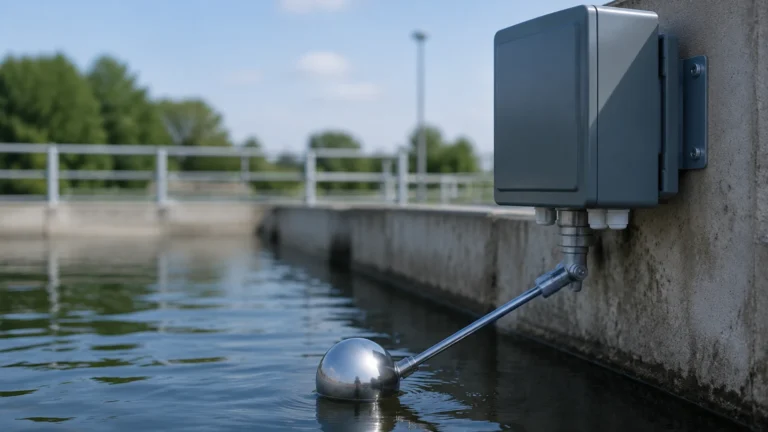
In pump lift stations, conductivity probes are used to start and stop pumps based on the water level. Because wastewater is highly conductive, these systems provide a low-maintenance alternative to float switches, which are prone to mechanical jamming due to debris.
Chemical Processing
For the storage of acids and bases, conductivity probes made of exotic alloys provide a reliable high-level alarm system. Since there are no moving parts, there is no risk of a mechanical hinge corroding or sticking.
Food and Beverage
Conductivity sensors are used to detect the interface between different fluids in a pipe (e.g., water vs. cleaning solution) or to monitor levels in mixing vats. Hygienic versions with Tri-clamp fittings and polished surfaces ensure compliance with sanitary standards.
Steam Boilers
Conductivity probes are a safety-critical component in steam boilers, used for low-water cut-off (LWCO) protection. They ensure the boiler does not operate without sufficient water, preventing catastrophic heat damage.
Frequently Asked Questions (FAQ)
Q: How often should conductivity probes be calibrated?
A: Conductivity probes themselves do not require calibration in the traditional sense, as they are simple electrodes. However, the sensitivity of the controller should be checked periodically, especially if the composition of the process liquid changes.
Q: Can I use conductivity controls for flammable liquids?
A: Only if the system is used in conjunction with an intrinsically safe (IS) barrier and the probes/housings are rated for hazardous areas. However, many flammable liquids (like gasoline) are non-conductive, making this technology unsuitable regardless of safety ratings.
Q: What is the maximum length for a rod probe?
A: Practically, rod probes are limited to about 3 to 4 meters due to weight and the risk of bending. For deeper requirements, cable-suspended probes are used.
Q: How do I handle foam in the tank?
A: If foam is causing false triggers, decrease the sensitivity on the controller. If the foam itself needs to be detected, increase the sensitivity.
Conclusion
Conductivity controls remain a cornerstone of level measurement technology due to their lack of moving parts, ease of installation, and high reliability in conductive media. By understanding the electrical principles and environmental constraints of the application, engineering teams can implement these systems to provide years of trouble-free service.
For a comprehensive overview of available technologies and technical specifications for various level measurement challenges, engineers can visit the Main Page to review product options and application support. Whether the requirement is for simple water level management or complex industrial automation, selecting the right probe and controller configuration is the first step toward a stable and safe process.