Conductivity Measurement Unit
Conductivity Measurement Unit
In industrial process control and liquid management, understanding the electrical properties of a medium is as critical as measuring its physical volume or pressure. The conductivity measurement unit serves as a fundamental metric for assessing water quality, chemical concentration, and the presence of dissolved solids. For engineers and plant operators, selecting the correct instrumentation requires a deep dive into how these units are derived, how they relate to specific applications, and how they integrate with broader systems like those found on the Main Page of industrial level measurement catalogs.
Electrical conductivity is the measure of a material's ability to allow the transport of an electric charge. In aqueous solutions, this ability is provided by dissolved ions. Consequently, conductivity is a direct indicator of the ionic strength of a solution. This article explores the technical nuances of the conductivity measurement unit, its application in level sensing, and the practical considerations for industrial implementation.
Understanding the Principles of Conductivity Measurement
Before discussing the specific units of measure, it is essential to understand the physical principles governing the measurement. Conductivity in liquids is typically measured using one of two methods: contacting (electrode-based) or inductive (toroidal).
Contacting Conductivity
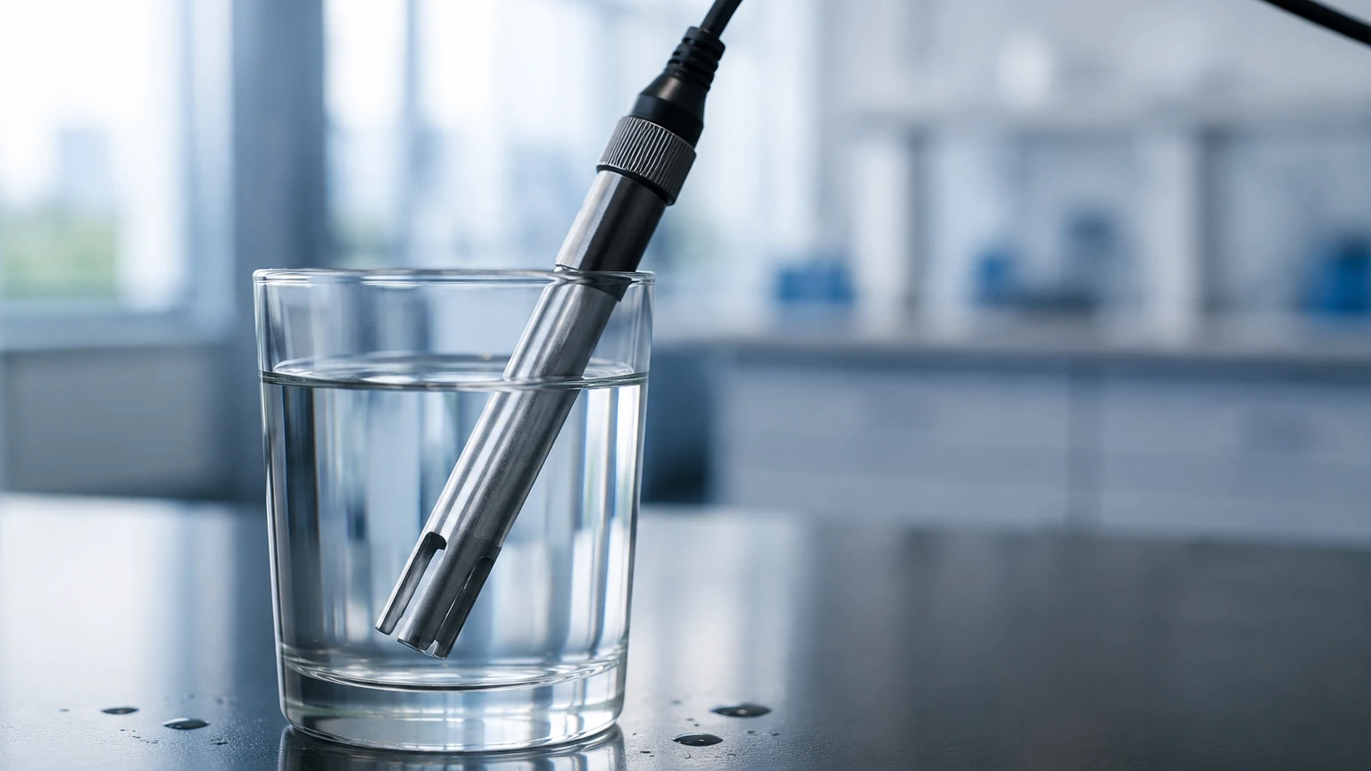
In a contacting sensor, two or more electrodes are placed in direct contact with the liquid. An alternating current (AC) voltage is applied between the electrodes. The ions in the liquid migrate toward the electrodes, creating a current. This current is proportional to the conductivity of the solution. To prevent polarization and electrode degradation, high-frequency AC is used rather than direct current (DC).
Inductive (Toroidal) Conductivity
Inductive sensors use two wire-wound metal toroids encapsulated in a plastic or ceramic housing. One toroid acts as a transmitter, creating an alternating magnetic field that induces a current in the surrounding conductive liquid. This liquid current, in turn, induces a current in the second (receiver) toroid. The strength of this secondary current is proportional to the conductivity of the liquid. This method is preferred for highly corrosive or fouling liquids where metal electrodes would fail.
Defining the Conductivity Measurement Unit
The standard SI unit for conductivity is Siemens per meter (S/m). However, in most industrial and laboratory applications, the conductivity measurement unit is expressed in sub-multiples to match the specific range of the liquid being analyzed.
Siemens and the Mho
Historically, the unit of conductance was the "mho" (ohm spelled backwards), reflecting that conductance is the reciprocal of resistance ($G = 1/R$). In the modern SI system, the mho has been replaced by the Siemens (S).
* Resistance ($R$): Measured in Ohms ($Ω$).
* Conductance ($G$): Measured in Siemens (S), where $1 S = 1/Ω$.
Conductivity vs. Conductance
Conductance is a property of a specific component or sample, whereas conductivity ($κ$) is an intrinsic property of the material itself. To convert measured conductance to conductivity, the geometry of the sensor must be accounted for using the "Cell Constant" ($K$).
$$κ = G × K$$
Where $K = L / A$ ($L$ is the distance between electrodes, and $A$ is the surface area of the electrodes). The resulting conductivity measurement unit is typically expressed as:
1. MicroSiemens per centimeter (µS/cm): Used for low-conductivity liquids like deionized water or boiler feed water.
2. MilliSiemens per centimeter (mS/cm): Used for high-conductivity liquids like seawater, acids, and industrial wastewater.
Relationship with Resistivity
In high-purity water applications, such as semiconductor manufacturing or pharmaceutical processing, it is more common to use resistivity units. Resistivity is the reciprocal of conductivity.
* Resistivity Unit: Ohm-centimeters ($Ω·cm$).
* Conversion: A conductivity of 0.055 µS/cm is equivalent to a resistivity of 18.2 MΩ·cm (the theoretical limit of pure water at 25°C).
Conductivity in Level Measurement Applications
While conductivity is a primary analytical parameter, it is also a vital mechanism for level detection. Conductive level switches utilize the liquid's conductivity to complete an electrical circuit. This is a robust and cost-effective method for point-level detection in conductive liquids.
How Conductive Level Switches Work
A low-voltage AC signal is applied to a probe (electrode). When the conductive liquid rises and touches the probe, it completes a circuit between the probe and the tank wall (if metal) or a reference electrode. This change in state triggers a relay, which can be used to start/stop pumps or trigger alarms. Because this method relies on the conductivity measurement unit being above a certain threshold (typically >5 µS/cm), it is not suitable for oils, hydrocarbons, or highly purified water.
Welk provides a range of industrial level instruments, including those designed for conductive media. For more complex applications where conductivity might vary or where non-contact measurement is required, engineers often refer to the Main Page for radar or ultrasonic alternatives.
Practical Selection Table for Conductivity Ranges
Choosing the right sensor and conductivity measurement unit scale depends entirely on the application. The following table provides typical ranges for common industrial fluids.
| Fluid Type | Typical Conductivity Range | Preferred Unit | Sensor Technology |
| :— | :— | :— | :— |
| Ultrapure Water | 0.055 to 1 µS/cm | µS/cm | Contacting (Low K) |
| Distilled Water | 0.5 to 5 µS/cm | µS/cm | Contacting (Low K) |
| Tap Water | 50 to 800 µS/cm | µS/cm | Contacting (Standard) |
| Wastewater | 0.5 to 5 mS/cm | mS/cm | Contacting or Inductive |
| Seawater | 30 to 60 mS/cm | mS/cm | Inductive |
| 10% Sulfuric Acid | ~400 mS/cm | mS/cm | Inductive |
| 31% Nitric Acid | ~850 mS/cm | mS/cm | Inductive |
Installation and Engineering Considerations
To ensure accurate data in the chosen conductivity measurement unit, several installation factors must be addressed. Errors in conductivity measurement are rarely due to the electronics; they are usually caused by physical installation issues or environmental factors.
1. Temperature Compensation
Conductivity is highly temperature-dependent. As temperature increases, the mobility of ions increases, leading to higher conductivity. Most industrial sensors include an internal temperature element (like a PT100 or PT1000) to provide Temperature Compensated Conductivity. The standard reference temperature is usually 25°C. Without compensation, a 1°C change in temperature can result in a 2% error in the conductivity reading.
2. Cell Constant Selection
The cell constant ($K$) must be matched to the range of the liquid:
* K = 0.01 or 0.1 cm⁻¹: For low conductivity (pure water).
* K = 1.0 cm⁻¹: For medium conductivity (general process water).
* K = 10.0 cm⁻¹: For high conductivity (concentrated chemicals).
3. Positioning and Flow
* Avoid Air Pockets: Sensors should be installed in a vertical pipe with upward flow or in the side of a tank where the electrodes are always submerged.
* Minimize Turbulence: Excessive bubbles can interfere with the electrical path, leading to unstable readings.
* Wall Interference: For inductive sensors, ensure there is adequate clearance between the sensor head and the pipe wall to prevent the magnetic field from interacting with the pipe material.
Limitations and Troubleshooting
While conductivity is a reliable measurement, certain conditions can compromise the accuracy of the conductivity measurement unit displayed on the controller.
* Fouling and Coating: In contacting sensors, the buildup of scale, oil, or biological growth on the electrodes acts as an insulator, artificially lowering the conductivity reading. Regular cleaning or switching to inductive sensors is necessary in these environments.
* Polarization: Using the wrong frequency or damaged electrodes can cause ions to build up near the electrode surface, creating a "false resistance" that skews the measurement.
* Non-Ionic Solids: Conductivity only measures dissolved ions. It cannot detect non-polar contaminants like oils, sugars, or suspended solids (TSS) that do not ionize in water.
Frequently Asked Questions (FAQs)
Q: Can I use a conductivity sensor to measure the level of oil?
A: No. Oils and hydrocarbons are non-conductive (dielectric). For oil level measurement, you should utilize technologies like guided wave radar or capacitive level transmitters, which can be found on the Main Page.
Q: How often should a conductivity sensor be calibrated?
A: Calibration frequency depends on the process. In clean water applications, every 6 to 12 months may suffice. In harsh chemical processes or wastewater, monthly verification against a known standard solution is recommended.
Q: What is the difference between TDS and Conductivity?
A: Total Dissolved Solids (TDS) is a measure of the mass of dissolved material. Conductivity is often used to estimate TDS by applying a conversion factor (typically 0.5 to 0.7). However, this factor varies depending on the specific ions present in the water.
Q: Why is my conductivity reading higher than expected in a closed loop?
A: This is often due to CO2 absorption from the air (which forms carbonic acid) or leaching of ions from pipe materials. In high-purity systems, ensure the system is properly sealed.
Conclusion
The conductivity measurement unit is a vital tool for industrial process optimization. Whether monitoring the purity of boiler feed water in µS/cm or controlling the concentration of a caustic cleaning solution in mS/cm, selecting the right technology and understanding the underlying physics is essential. By integrating conductivity data with robust level measurement solutions, facilities can achieve higher levels of automation, safety, and efficiency. For technical specifications on sensors that interface with these measurement units, consulting a specialized manufacturer like Welk ensures that the equipment is matched to the specific chemical and physical demands of the application.