Continuous Level Transmitter
Continuous Level Transmitter
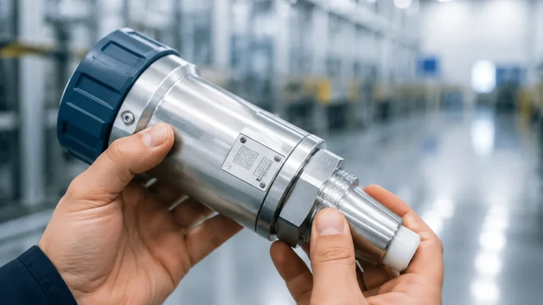
In industrial process control, the ability to monitor the exact volume or height of a substance within a vessel at any given moment is critical for operational efficiency, safety, and inventory management. A continuous level transmitter is a device designed to provide an uninterrupted output signal—typically 4-20mA, HART, or Modbus—representing the fluid level across the entire measurement span. Unlike point level switches that only indicate whether a level has reached a specific threshold, continuous transmitters allow for sophisticated automation, trend analysis, and precise dosing.
Selecting the appropriate continuous level transmitter requires a deep understanding of the underlying measurement principles, as the physical properties of the media and the environmental conditions of the tank significantly impact performance. This guide examines the primary technologies used in modern industrial level measurement, their selection criteria, and practical installation considerations.
Measurement Principles of Continuous Level Transmitters
Before selecting a device, it is essential to understand how different technologies interact with the process media. Each principle has distinct advantages and limitations regarding accuracy, media compatibility, and environmental resistance.
Radar Level Measurement (ToF)
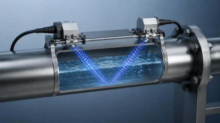
Radar transmitters utilize Time-of-Flight (ToF) technology. They emit high-frequency electromagnetic pulses (typically in the 26 GHz or 80 GHz range) that travel at the speed of light. These pulses reflect off the surface of the medium and return to the sensor. The transmitter calculates the distance based on the time interval between transmission and reception.
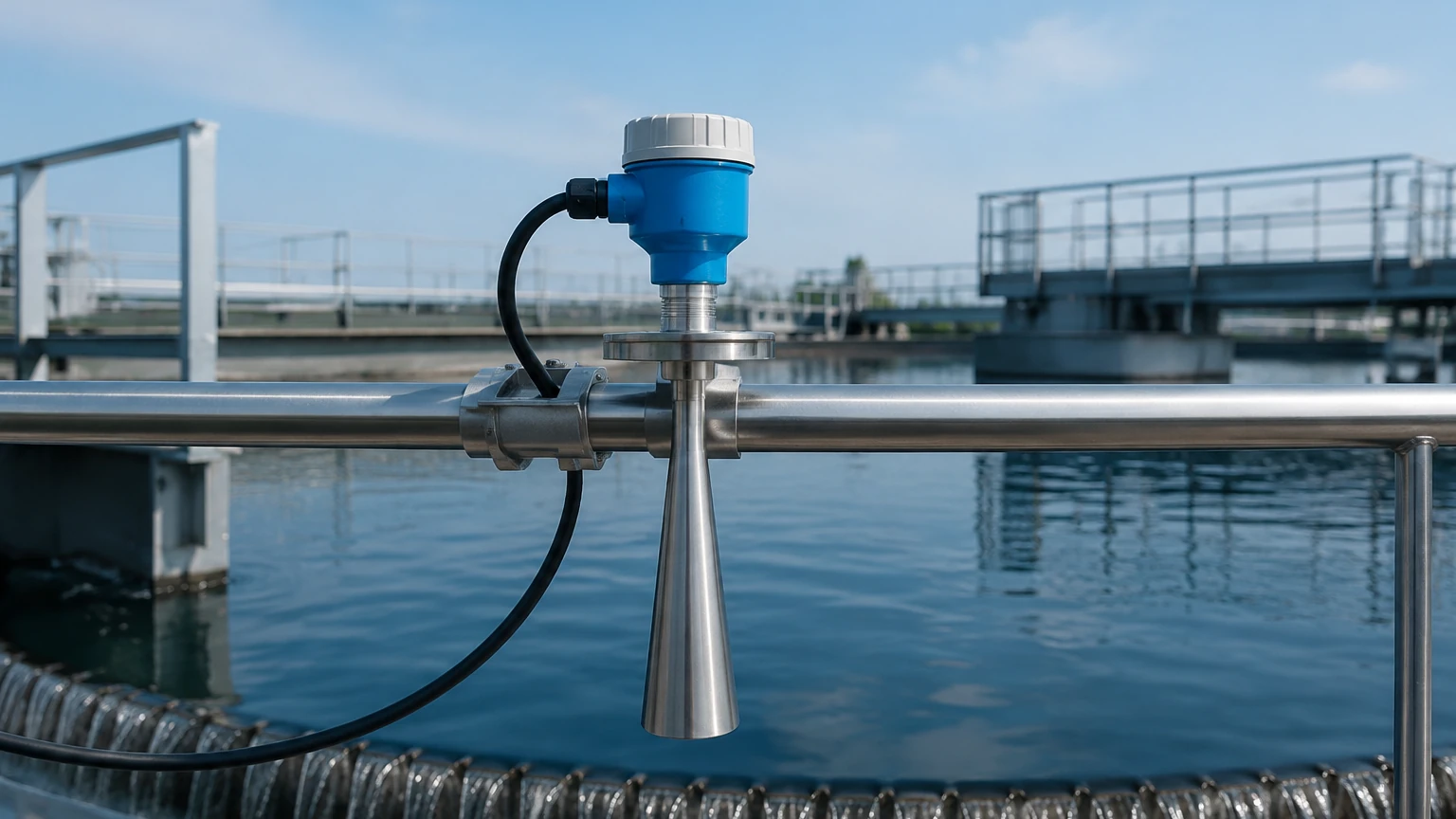
* Non-Contact Radar: These sensors are mounted at the top of the tank and do not touch the media. They are ideal for corrosive, hot, or hygienic applications. High-frequency 80 GHz radar offers a narrow beam angle, which is particularly useful in vessels with internal obstructions like agitators or heating coils.
* Guided Wave Radar (GWR): GWR uses a physical probe (cable or rod) to guide the microwave pulse to the surface. This method is highly effective for low-dielectric liquids and applications where foam, steam, or heavy turbulence might interfere with a non-contact signal.
Ultrasonic Level Measurement
Ultrasonic transmitters emit high-frequency sound waves. Similar to radar, they measure the time it takes for the sound to bounce off the surface and return. Because sound requires a medium to travel through, these sensors are affected by air temperature, pressure, and gas composition. Most modern ultrasonic units include integrated temperature compensation to maintain accuracy. They are widely used in water treatment and open-channel flow applications due to their cost-effectiveness.
Hydrostatic Level Measurement
Hydrostatic transmitters measure the pressure exerted by a liquid column at the bottom of a tank. The principle is based on the formula: $P = \rho \cdot g \cdot h$, where $P$ is pressure, $\rho$ is the density of the liquid, $g$ is gravity, and $h$ is the height of the liquid.
* Submersible Transmitters: These are lowered into the liquid and are common in deep wells or reservoirs.
* Flanged/Threaded Transmitters: These are mounted to the side of the tank at the lowest measurement point.
This technology is highly reliable but requires a constant media density to maintain accuracy. If the density changes due to temperature fluctuations or chemical mixing, the level reading will drift unless compensated.
Magnetic Level Transmitters
Often used in conjunction with a magnetic level gauge, these transmitters utilize a float containing a magnet. As the float moves with the liquid level, it interacts with a sensing element (usually a magnetostrictive wire or a series of reed switches) mounted outside the chamber. This provides a continuous electrical output while offering a clear visual indication for operators on-site.
Technology Selection Table
Choosing a continuous level transmitter depends on the specific requirements of the application. The following table provides a comparison of the most common technologies.
| Technology | Accuracy | Media Type | Max Temperature | Max Pressure | Best For |
| :— | :— | :— | :— | :— | :— |
| Non-Contact Radar | ±1 mm to ±5 mm | Liquids & Solids | Up to +450°C | Up to 160 bar | Corrosive media, high-temp, hygienic |
| Guided Wave Radar | ±2 mm | Liquids & Solids | Up to +400°C | Up to 400 bar | Low dielectric liquids, foam, turbulence |
| Ultrasonic | ±0.25% of range | Primarily Liquids | Up to +80°C | Up to 3 bar | Water, wastewater, simple storage |
| Hydrostatic | ±0.1% to ±0.5% | Liquids | Up to +100°C | Dependent on sensor | Deep wells, vented tanks, constant density |
| Magnetic | ±1 mm to ±5 mm | Liquids | Up to +400°C | Up to 320 bar | High pressure, visual + remote monitoring |
For a comprehensive look at specific hardware configurations and technical specifications for these technologies, engineers can Review product options and application support to match a device to their process conditions.
Key Evaluation Criteria for Project Planning
When specifying a continuous level transmitter, the following factors must be confirmed to ensure the longevity and reliability of the instrument:
1. Media Characteristics
* Dielectric Constant ($ε_r$): Crucial for radar. Low dielectric liquids (like oils) reflect less energy than high dielectric liquids (like water). GWR is often required for $ε_r < 1.9$.
* Viscosity and Coating: Sticky or viscous media can build up on probes or sensor faces. Non-contact radar or ultrasonic sensors are preferred here to avoid maintenance issues.
* Corrosivity: Ensure the wetted materials (316L Stainless Steel, PTFE, Hastelloy, etc.) are compatible with the chemical composition of the fluid.
2. Process Conditions
* Vapor and Dust: Heavy steam or dust can attenuate ultrasonic signals. Radar is generally immune to these conditions.
* Vacuum: Ultrasonic sensors cannot function in a vacuum because sound waves require a medium. Radar is the standard choice for vacuum applications.
* Turbulence and Foam: Agitators create surface turbulence that can scatter signals. Foam acts as an absorber for both ultrasonic and non-contact radar; GWR is typically the most robust solution for foamy surfaces.
3. Vessel Geometry
* Blocking Distance (Dead Zone): Every transmitter has a minimum distance near the sensor where it cannot measure accurately. This must be accounted for when calculating the maximum fill level.
* Internal Obstructions: Ladders, pipes, and agitators can create false echoes. Modern transmitters use "False Echo Suppression" software to map out these obstructions, but proper placement is still the first line of defense.
Installation Considerations and Best Practices
Proper installation is as important as selecting the right technology. Failure to follow manufacturer guidelines often leads to signal loss or inaccurate readings.
1. Nozzle Height and Diameter: For non-contact radar and ultrasonic sensors, the nozzle should be as short and wide as possible to prevent the signal from reflecting off the nozzle walls. If a long nozzle is unavoidable, ensure the sensor horn extends past the nozzle bottom.
2. Mounting Position: Avoid mounting the transmitter in the center of a tank with a domed roof, as this can concentrate reflected signals and cause interference. Also, ensure the sensor is not placed directly above the fill inlet, as the falling stream will disrupt the measurement.
3. Orientation: For hydrostatic sensors, ensure the diaphragm is not susceptible to sediment buildup. For radar, the antenna must be perpendicular to the liquid surface for maximum signal return.
4. Stilling Wells and Bypass Chambers: In applications with extreme turbulence or heavy foam, mounting the continuous level transmitter inside a stilling well or an external bypass chamber can provide a calm surface for accurate measurement.
Common Risks and Limitations
While continuous level transmitters are highly advanced, they are not "one-size-fits-all" solutions.
* Signal Attenuation: In ultrasonic systems, changes in gas composition (e.g., high CO2 concentration) change the speed of sound, leading to errors of up to 10% if not calibrated for the specific gas.
* Density Sensitivity: Hydrostatic transmitters are purely pressure-based. If a process involves mixing different liquids or significant temperature swings that change the density, the transmitter will report an incorrect level unless a secondary pressure sensor is used for differential calculation.
* Build-up on GWR Probes: While GWR is robust, significant conductive coating on the probe can cause a "bridge" between the probe and the tank wall, leading to a fixed high-level reading.
Frequently Asked Questions (FAQ)
Q: Can a continuous level transmitter be used for solids?
A: Yes. Radar (both non-contact and guided) is excellent for powders, grains, and aggregates. However, the angle of repose of the solid material must be considered, as the signal may reflect away from the sensor if the surface is steeply sloped.
Q: What is the difference between 2-wire and 4-wire transmitters?
A: 2-wire transmitters use the same two wires for both power and the 4-20mA signal, making them easier to install. 4-wire transmitters have separate pairs for power and signal, which is often necessary for high-power devices like certain radar units or those with integrated heaters.
Q: How do I handle measurement in tanks with agitators?
A: The best approach is to use a high-frequency (80 GHz) radar with a narrow beam to avoid the blades, or to use a guided wave radar if the probe can be safely secured. Software-based echo masking can also be used to ignore the moving blades.
Q: Is calibration required for all transmitters?
A: Most digital transmitters come pre-calibrated from the factory, but "wet calibration" or field adjustment is recommended to align the 4mA (empty) and 20mA (full) points with the actual vessel dimensions.
Conclusion
Implementing a continuous level transmitter is a foundational step in modernizing industrial processes. By moving beyond simple point-level detection, facilities gain the data necessary for optimized supply chains, reduced waste, and enhanced safety. Whether the application involves a simple water tank or a high-pressure chemical reactor, understanding the physics of the measurement—be it radar, ultrasonic, or hydrostatic—is the key to long-term reliability. For technical assistance in selecting the specific model for your facility, visiting the Main Page of a specialized manufacturer provides access to detailed engineering data and customization options.